Table of Contents
Advertisement
Quick Links
AN2019-04 EVAL-M3-IM564 User Manual
EVAL-M3-IM564 User Manual
iMOTION™ Modular Application Design Kit
About this document
Scope and purpose
This user manual provides an overview of the evaluation board EVAL-M3-IM564 including its main features, key
data, pin assignments and mechanical dimensions.
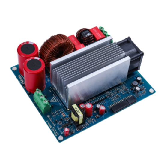
EVAL-M3-IM564 is an evaluation board as part of the iMOTION™ modular application design kit. This power
board includes a PFC integrated 3-phase CIPOS™ Mini intelligent power module (IPM) for motor drive
applications. In combination with the control board equipped with the M3 30-pin interface connector such as
EVAL-M3-102T, it features and demonstrates Infineon's CIPOS™ Mini IPM technology and advanced motion
control engine (MCE 2.0) technology for permanent magnet motors drive over the full speed range.
The inverter section has 600 V of voltage and 20 A of current rating, and the PFC section has 600 V of voltage and
20 A of current rating. It is optimized to major home appliances like air conditioners and low power motor dirve
applications with high-frequency switching operation of power factor correction.
This evaluation board EVAL-M3-IM564 was developed to support customers during their first steps designing
applications with CIPOS™ Mini PFC integrated IPM IM564-X6D/IM564-X6DS and running any permanent magnet
motor via sensorless sinusoidal control.
Intended audience
This user manual is intended for all technical specialists who know motor control and high-power electronics
converters. The board is intended to be used under laboratory conditions.
Attention:
The Evaluation Boards and Reference Boards as well as the information in this document are
solely intended to support designers of applications in evaluating the use of products from
Infineon Technologies for their intended applications.
Environmental conditions have been considered in the design of the Evaluation Boards and
Reference Boards provided by Infineon Technologies. The design of the Evaluation Boards
and Reference Boards has been tested by Infineon Technologies only as described in this
document. The design is not qualified in terms of safety requirements, manufacturing and
operation over the entire operating temperature range or lifetime.
The Evaluation Boards and Reference Boards provided by Infineon Technologies are subject
to functional testing only under typical load conditions. Evaluation Boards and Reference
Boards are not subject to the same procedures as regular products regarding returned
material analysis (RMA), process change notification (PCN) and product discontinuation (PD).
Evaluation Boards and Reference Boards are not commercialized products, and are solely
intended for evaluation and testing purposes. In particular, they shall not be used for
reliability testing or production. The Evaluation Boards and Reference Boards may therefore
not comply with CE or similar standards (including but not limited to the EMC Directive
2004/EC/108 and the EMC Act) and may not fulfill other requirements of the country in which
they are operated by the customer. The customer shall ensure that all Evaluation Boards and
User Manual
www.infineon.com
Please read the Important Notice and Warnings at the end of this document
page 1 of 47
Revision 1.4
2020-07-16
Advertisement
Table of Contents

Related Manuals for Infineon iMOTION EVAL-M3-IM564


Summary of Contents for Infineon iMOTION EVAL-M3-IM564
-
Page 1: About This Document
Environmental conditions have been considered in the design of the Evaluation Boards and Reference Boards provided by Infineon Technologies. The design of the Evaluation Boards and Reference Boards has been tested by Infineon Technologies only as described in this document. The design is not qualified in terms of safety requirements, manufacturing and operation over the entire operating temperature range or lifetime. - Page 2 Infineon Technologies shall not be responsible for any damages resulting from the use of the Evaluation Boards and Reference Boards and/or from any information provided in this document.
-
Page 3: Safety Precautions
EVAL-M3-IM564 User Manual iMOTION™ Modular Application Design Kit Introduction Safety precautions Please note the following warnings regarding the hazards associated with development systems. Table 1 Safety precautions Warning: The DC link potential of this board is up to 400 V . -
Page 4: Table Of Contents
EVAL-M3-IM564 User Manual iMOTION™ Modular Application Design Kit Introduction Table of contents About this document ........................1 Safety precautions .......................... 3 Table of contents ..........................4 Introduction .......................... 5 Main features of EVAL-M3-IM564 ....................7 EVAL-M3- IM564 board specifications ..................... 8 Pin assignment ............................ -
Page 5: Introduction
MADK M1 interface connector to control board. This board is equipped with a 30-pin M3 connector and is intended for single-motor control only. This evaluation board is designed to provide an easy-to-use power stage based on the Infineon's CIPOS™ Mini intelligent power module (IPM). The board is equipped with all assembly groups for sensorless field-oriented control (FOC). - Page 6 EVAL-M3-IM564 User Manual iMOTION™ Modular Application Design Kit Introduction Evaluation boards are not subject to the same procedures as regular products regarding returned material analysis (RMA), process change notification (PCN) and product discontinuation (PD). Evaluation boards are intended to be used under laboratory conditions by technical specialists only. User Manual 6 of 47 Revision 1.4...
-
Page 7: Main Features Of Eval-M3-Im564
EVAL-M3-IM564 is an evaluation board for motor drive applications with single-phase, integrated PFC and 3- phase IPM. Combined in a kit with one of the available MADK control board options, it demonstrates Infineon’s motion control IC and IPM technology for motor drives with single-phase PFC. -
Page 8: Eval-M3- Im564 Board Specifications
EVAL-M3-IM564 User Manual iMOTION™ Modular Application Design Kit Main features of EVAL-M3-IM564 EVAL-M3- IM564 board specifications Table 2 depicts the important specifications of the evaluation board EVAL-M3-IM564. Table 2 EVAL-M3-IM564 board specifications Parameters Values Conditions / comments Input Voltage 165 - 265 V lower AC input, less motor power output 13.3 A input 165 V... - Page 9 EVAL-M3-IM564 User Manual iMOTION™ Modular Application Design Kit Main features of EVAL-M3-IM564 Parameters Values Conditions / comments Configured by either PFC current sensing 22 A peak PFC OCP2 resistor RS3, or adapting comparator threshold divider resistor R5/R7 or R4/R8 20 A Configured by MCEWizard only, OPA output peak Inverter OCP1...
- Page 10 EVAL-M3-IM564 User Manual iMOTION™ Modular Application Design Kit Main features of EVAL-M3-IM564 Figure 2 points out the functional groups on the top side of the EVAL-M3-IM564 evaluation board. 1. J1 - AC Input connector 2. Relay, NTC and fuse 3. PFC gate drive and PFC overcurrent protection circuits 4.
-
Page 11: Pin Assignment
EVAL-M3-IM564 User Manual iMOTION™ Modular Application Design Kit Main features of EVAL-M3-IM564 Pin assignment General information about the connectors of the EVAL-M3-IM564 evaluation board is reported. Table 3 includes the details of the AC input connector J1. Table 3 J1- AC Line connector S. - Page 12 EVAL-M3-IM564 User Manual iMOTION™ Modular Application Design Kit Main features of EVAL-M3-IM564 Name Pin name connectors 15 V power supply PFCG0 3.3 V compatible logic input for PFC gate driver IC Ground PFCG1 Not used +3.3 V On board 3.3 V supply PFCGK PFC Gatekill signal –...
-
Page 13: Getting Started With Eval-M3-Im564
EVAL-M3-IM564 User Manual iMOTION™ Modular Application Design Kit Getting started with EVAL-M3-IM564 Getting started with EVAL-M3-IM564 In order to run the motor system, a combination of the iMOTION™ MADK power board (EVAL-M3-IM564) and the matching MADK control board is required. The iMOTION™ software tools, MCEDesigner and MCEWizard, are also required in order to initially set up the system, as well as to control and fine-tune the system performance to match users’... - Page 14 3. Get the latest “IMC102T-F064 MCE Software Package” available on www.infineon.com/imotion-software website. (Infineon iMOTION™ control IC IMC102T-F064 is used for control board EVAL-M3-102T). 4. Connect motor phase outputs to the motor. 5. Use MCEWizard to enter the motor and evaluation board hardware parameters, and click button “Export to Designer file (.txt)”...
-
Page 15: Imotion™ Development Tools And Software
“Welcome Page” for MCEWizard, where the MADK control board or power board can be selected via the pull-down list. Infineon continues to release new MADK controller and power boards. Therefore, it could happen that some of the newest power boards are not pre-configured in the MCEWizard tool, and cannot be selected via the pull-down menu. - Page 16 EVAL-M3-IM564 User Manual iMOTION™ Modular Application Design Kit Getting started with EVAL-M3-IM564 There are very limited numbers of parameters which are specific to the control board or power board hardware. Table 6 provides the MCEWizard setup overview for hardware related parameters. Similar tables will be available in each control board’s User Manual.
- Page 17 EVAL-M3-IM564 User Manual iMOTION™ Modular Application Design Kit Getting started with EVAL-M3-IM564 Page Parameter Value Comment Question 115 AC Voltage Sensing Low Refer to control board user manual 15 kΩ by default for Resistor EVAL-M3-102T Question 117 PFC Gate Driver Polarity Low High is active Side Question 118...
-
Page 18: Mcedesigner Setup Overview
EVAL-M3-IM564 User Manual iMOTION™ Modular Application Design Kit Getting started with EVAL-M3-IM564 3.2.2 MCEDesigner setup overview After installing MCEDesigner installer, there is a shortcut for MCEDesigner on the Windows desktop. Double- click the shortcut to open MCEDesigner, and then open “IMC102T_xx.irc” file, and resize the windows for better display, as shown in Figure 7. - Page 19 Figure 9 Program firmware and parameter in “Program IMC Controller” pop-up window All the latest firmware files for different types of iMOTION control ICs are available for download via the Infineon iMOTION website (http://www.infineon.com/imotion-software). User Manual 19 of 47 Revision 1.4...
-
Page 20: Hardware Description Of Eval-M3-Im564
EVAL-M3-IM564 User Manual iMOTION™ Modular Application Design Kit Hardware description of EVAL-M3-IM564 Hardware description of EVAL-M3-IM564 To meet individual customer requirements and make the EVAL-M3-IM564 evaluation board a basis for development or modification, all necessary technical data like schematics, layout and components are included in this chapter. -
Page 21: Hardware Modification For Ac Voltage Sensing To Work With Irmcf188
EVAL-M3-IM564 User Manual iMOTION™ Modular Application Design Kit Hardware description of EVAL-M3-IM564 The configuration of PFC topology in MCEWizard is shown in Figure 12. Figure 12 Vac sensing method configuration for EVAL-M3-102T and EVAL-M3-IM564 The high-side resistors R1 and R2 or R9 and R10 for the AC voltage sensing resistor divider on the power board EVAL-M3-IM564 is 2000 kΩ, and should be configured in MCEWizard as shown in Figure 13. -
Page 22: Pfc External Current Feedback Configuration And Calculation
EVAL-M3-IM564 User Manual iMOTION™ Modular Application Design Kit Hardware description of EVAL-M3-IM564 188 or IRMCF188, power board EVAL-M3-IM564 should be modified by assembling 1 MΩ AC voltage sensing resistors R2A and R10A and removing the resistors R2 and R10. 4.1.3 PFC external current feedback configuration and calculation The PFC shunt resistor RS3 is 5 mΩ... -
Page 23: Pfc Overcurrent Protection Circuit And Pfc Gatekill Configuration
EVAL-M3-IM564 User Manual iMOTION™ Modular Application Design Kit Hardware description of EVAL-M3-IM564 4.1.4 PFC overcurrent protection circuit and PFC Gatekill configuration OCP1 of PFC protection circuit for EVAL-M3-IM564 as shown in Figure 16, the PFC current-sensing input polarity is non-inverting, so please reset the protection reference voltage of EVAL-M3-102T evaluation board. 3.3V iMOTION R8 change to 470 ohm... -
Page 24: Inverter Section Using Cipos™ Mini Ipm
EVAL-M3-IM564 User Manual iMOTION™ Modular Application Design Kit Hardware description of EVAL-M3-IM564 × × The calculation formula is as follows, = 3.3 × Where, 3.3 × × − = 22 × If a larger PFC current-protection setting value is needed, please reconfigure the adapting comparator threshold divider resistor R5/R7 or R4/R8. -
Page 25: Dc Bus Sensing And Mcewizard Configuration
EVAL-M3-IM564 User Manual iMOTION™ Modular Application Design Kit Hardware description of EVAL-M3-IM564 4.2.1 DC bus sensing and MCEWizard configuration Pin 14 and pin 26 of connector J3 provide access to the DC-link voltage DCBsense. Three possible feedback cases are associated with these pins. Figure 19 provides the DC bus sense resistor details. By default, the resistor R21 is not mounted on EVAL-M3-IM564. -
Page 26: Motor External Current Feedback Configuration And Calculation
EVAL-M3-IM564 User Manual iMOTION™ Modular Application Design Kit Hardware description of EVAL-M3-IM564 4.2.2 Motor external current feedback configuration and calculation The current input value is a product of the shunt resistance in milliohms and gain of external current sense amplifier for EVAL-M3-102T, as shown in Figure 21. Figure 21 Current shunt feedback and sample timing for EVAL-M3-102T The external amplifier gain circuit can be found in the schematics or user manual for the control board (for... -
Page 27: Inverter Overcurrent Protection And Motor Gatekill Configuration
EVAL-M3-IM564 User Manual iMOTION™ Modular Application Design Kit Hardware description of EVAL-M3-IM564 = 10 Based on this calculation, the motor current input scaling of EVAL-M3-IM564 is 100 mV/A. Please use the same procedure to calculate the current input for other combinations of MADK boards, and enter it into MCEWizard. The MCEWizard setting as shown in Figure 23. -
Page 28: Thermistor/Ntc Characteristics And Protection Calculation
EVAL-M3-IM564 User Manual iMOTION™ Modular Application Design Kit Hardware description of EVAL-M3-IM564 types of gatekill input source (as shown in Figure 25). Either input source, iMOTION™ control IC will stop the motor when the gatekill signal is active. In order to get high power output for this MADK board, the board uses a very low resistance R with 10 mΩ. - Page 29 EVAL-M3-IM564 User Manual iMOTION™ Modular Application Design Kit Hardware description of EVAL-M3-IM564 Value Description Condition Symbol Unit Resistor = 100°C 5.199 5.388 5.576 kΩ Resistor = 110°C 3.856 4.009 4.163 kΩ Resistor = 120°C 2.900 3.024 3.149 kΩ Resistor = 125°C 2.527 2.639 2.751...
-
Page 30: Overtemperature Hardware Protection Circuit
EVAL-M3-IM564 User Manual iMOTION™ Modular Application Design Kit Hardware description of EVAL-M3-IM564 4.3.2 Overtemperature hardware protection circuit The VFO pin not only provides direct access to the NTC, but also indicates a module failure in case of under- voltage at pin VDD or in case of triggered overcurrent detection at ITRIP. In these evaluation design kits EVAL- M3-IM564 and EVAL-M3-102T, the VFO pin is directly connected to the gatekill pin for controller IC IMC102T. -
Page 31: System Thermal Resistance Testing
EVAL-M3-IM564 User Manual iMOTION™ Modular Application Design Kit Hardware description of EVAL-M3-IM564 =5.576 kohm, and the shutdown value should be =10.593 kohm, and the shutdown value If the setting temperature is 100 °C, 2.33 V. If the setting temperature is 80 °C, should be 2.36 V. -
Page 32: System Power Output Capability
EVAL-M3-IM564 User Manual iMOTION™ Modular Application Design Kit Hardware description of EVAL-M3-IM564 ∆ − Thus we get the following formula: × According to the test set-up, the test results are shown in Figure 30 below. The IPM case temperature is detected for about one hour, until the temperature is stable. -
Page 33: Auxiliary Power Supply
EVAL-M3-IM564 User Manual iMOTION™ Modular Application Design Kit Hardware description of EVAL-M3-IM564 With the MADK output power increasing, the IPM DCB PFC test point and IGBT test point temperature are monitored. The final test results are shown in Figure 31. Auxiliary power supply Figure 32 depicts the schematic of the auxiliary power supply for the EVAL-M3-IM564 board. -
Page 34: Schematics For Eval-M3- Im564
EVAL-M3-IM564 User Manual iMOTION™ Modular Application Design Kit Hardware description of EVAL-M3-IM564 Schematics for EVAL-M3- IM564 The PFC section schematic for EVAL-M3- IM564 is provided in Figure 33. Figure 33 PFC section schematics for EVAL-M3- IM564 The inverter section schematic for EVAL-M3- IM564 is provided in Figure 34. Figure 34 Inverter section schematics for EVAL-M3- IM564 User Manual... - Page 35 EVAL-M3-IM564 User Manual iMOTION™ Modular Application Design Kit Hardware description of EVAL-M3-IM564 The auxiliary power supply section schematic for EVAL-M3- IM564 is provided in Figure 35. Figure 35 Auxiliary power supply section schematics for EVAL-M3- IM564 User Manual 35 of 47 Revision 1.4 2020-07-16...
-
Page 36: Pcb Layout For Eval-M3- Im564
EVAL-M3-IM564 User Manual iMOTION™ Modular Application Design Kit Hardware description of EVAL-M3-IM564 PCB layout for EVAL-M3- IM564 The layout of this board can be used for different voltage or power classes. By default, the PCB has two electrical layers with 35 µm copper, and dimensions of 148 mm × 165 mm. The PCB board thickness is 1.6 mm. You can contact our technical support team for more detailed information and the latest Gerber files. - Page 37 EVAL-M3-IM564 User Manual iMOTION™ Modular Application Design Kit Hardware description of EVAL-M3-IM564 Figure 37 depicts the bottom assembly print of the evaluation board. Figure 37 Bottom assembly print of the EVAL-M3-IM564 evaluation board User Manual 37 of 47 Revision 1.4 2020-07-16...
- Page 38 EVAL-M3-IM564 User Manual iMOTION™ Modular Application Design Kit Hardware description of EVAL-M3-IM564 The top layer routing of the PCB is provided in Figure 38. Figure 38 Top layer routing of the EVAL-M3-IM564 User Manual 38 of 47 Revision 1.4 2020-07-16...
- Page 39 EVAL-M3-IM564 User Manual iMOTION™ Modular Application Design Kit Hardware description of EVAL-M3-IM564 Figure 39 illustrates the bottom layer routing of the PCB. Figure 39 Bottom layer routing of the EVAL-M3-IM564 User Manual 39 of 47 Revision 1.4 2020-07-16...
-
Page 40: Bill Of Material
EVAL-M3-IM564 User Manual iMOTION™ Modular Application Design Kit Bill of material Bill of material Table 8 provides the complete bill of materials for the EVAL-M3-IM564. Table 8 Bill of materials No. Qty Part description Designator Part number Manufacturer C1, C18, C1210C104KBRAC78 CAP CER 0.1UF 630V X7R 1210 C57, C58,... - Page 41 Wurth Electronics Inc. BRIDGE RECT 1PHASE 1200V 25A GBJ2512 Diodes Incorporated DIODE SCHOTTKY 30V 200MA SC79- D2, D3, D9, BAT5402VH6327XTS Infineon Technologies DIODE SCHOTTKY 20V 1A SOD123L MBR120ESFT1G ON Semiconductor DIODE SCHOTTKY 150V 2A DO15 MBR2150VGTR-E1 Diodes Incorporated DIODE GEN PURP 1KV 1A SMA...
- Page 42 EVAL-M3-IM564 User Manual iMOTION™ Modular Application Design Kit Bill of material No. Qty Part description Designator Part number Manufacturer FERRITE BEAD 300 OHM 0805 1LN 742792035 Wurth Electronics Inc. FIXED IND 47UH 1.55A 136 MOHM 74404084470 Wurth Electronics Inc. LED1 150080RS75000 Wurth Electronics Inc.
- Page 43 EVAL-M3-IM564 User Manual iMOTION™ Modular Application Design Kit Bill of material No. Qty Part description Designator Part number Manufacturer R20, R32, R34, R35, RES SMD 2K OHM 1% 1/10W 0603 R36, R37, RC0603FR-072KL Yageo R38, R39, RES SMD 27K OHM 5% 1/10W 0603 RC0603JR-0727KL Yageo RES SMD 249 OHM 1% 1/4W 1206...
- Page 44 U1, U8 LMV331IDBV Texas Instruments IC DRIVER LOW SIDE 1.5A SOT23-5 IRS44273LTRPBF Diodes Incorporated IFX1117MEV33HTMA IC REG LINEAR 3.3V 1A SOT223-4 Infineon Technologies ICE5QR4770AGXUMA IC CTLR QUASI-RES 12SOIC Infineon Technologies OPTOISOLATOR 5KV TRANSISTOR FOD817BSD ON Semiconductor 4SMD IC VREF SHUNT ADJ SOT23-3...
-
Page 45: Reference
All the CIPOS™ IPM’s datasheets and documents are available at www.infineon.com/IPM. Attention: Infineon’s product registration is online now. Register your board, and download more information. 3 easy steps to register: 1. Go to www.Infineon.com/ login to myinfineon 2. Click on “Product Registration”... -
Page 46: Revision History
EVAL-M3-IM564 User Manual iMOTION™ Modular Application Design Kit Reference Revision history Document Date of release Description of changes version 2019-09-17 First release 2019-12-09 Updated BOM List §6 2020-01-17 Updated BOM List §6 2020-02-16 Updated MCEWizard & MCEDesigner screenshot (V2.1.2.0) 2020-07-16 Update schematic and PCB layout for improvement of noise issue User Manual 46 of 47... - Page 47 Infineon Technologies hereby disclaims dangerous substances. For information on the types © 2020 Infineon Technologies AG. any and all warranties and liabilities of any kind in question please contact your nearest Infineon All Rights Reserved. (including without limitation warranties of non- Technologies office.
Need help?
Do you have a question about the iMOTION EVAL-M3-IM564 and is the answer not in the manual?
Questions and answers