Bender LINETRAXX PEM330 Manual
Universal measuring device
Hide thumbs
Also See for LINETRAXX PEM330:
- Manual (6 pages) ,
- Quick start (4 pages) ,
- Quick start (4 pages)

Subscribe to Our Youtube Channel
Related Manuals for Bender LINETRAXX PEM330


Summary of Contents for Bender LINETRAXX PEM330
- Page 1 Manual PEM330/PEM333/PEM333-P Universal measuring device B 9310 0330 Software version starting 1.20.13 B 9310 0331 B 9310 0333 B 9310 0334 B 9310 0335 B 9310 0336 PEM330-333_D00004_01_M_XXEN/08.2015...
- Page 2 Bender GmbH & Co. KG Londorfer Str. 65 • 35305 Gruenberg • Germany Postfach 1161 • 35301 Gruenberg • Germany Tel.: +49 6401 807-0 Fax: +49 6401 807-259 Email: info@bender.de www.bender.de © Bender GmbH & Co. KG All rights reserved.
-
Page 3: Table Of Contents
Table of Contents 1. Making effective use of this document ............7 How to use this manual ................. 7 Technical support: Service and support ..........8 Training courses ....................9 Delivery conditions, guarantee, warranty and liability ....10 2. Safety ........................ 11 Intended use .................... - Page 4 Table of Contents 4.4.3 Connection of measuring current transformers ........ 22 Instructions for connection ............... 22 Wiring diagram ....................22 4.6.1 PEM330 ......................23 4.6.2 PEM333 ......................24 4.6.3 PEM333-P ......................26 Connection diagram voltage inputs ............28 4.7.1 Three-phase 4-wire system (TN, TT, IT systems) ......... 28 4.7.2 Three-phase 3-wire system ................
- Page 5 Table of Contents 6.8.3 Button „ENERGY“ ................... 48 Setup using the "SETUP" button .............. 49 6.9.1 "SETUP": Meaning of the buttons ............49 6.9.2 SETUP: Overview diagram menu ............. 50 6.10 Setup: Setting possibilities ................. 51 7. Application/inputs and outputs ..............59 Digital inputs (PEM333…...
- Page 6 Table of Contents 8.9.3 Data structure Max/Min log ............... 93 8.10 Time setting ..................... 94 8.11 DOx control ..................... 95 8.12 Universal measuring device information ..........96 9. Technical data ....................99 Standards and certifications ..............102 Ordering information ................102 INDEX .........................
-
Page 7: Making Effective Use Of This Document
1. Making effective use of this document 1. 1 How to use this manual This manual is intended for experts in electrical engineering and electronics! In order to make it easier for you to find specific text passages or references in this manual and for reasons of comprehensibility, important information is emphasized by symbols. -
Page 8: Technical Support: Service And Support
Making effective use of this document 1. 2 Technical support: Service and support For commissioning and troubleshooting Bender offers you: First Level Support Technical support by phone or e-mail for all Bender products All questions about customer applications Commissioning ... -
Page 9: Training Courses
**Mo-Thu 7.00 a.m. - 8.00 p.m., Fr 7.00 a.m. - 13.00 p.m 1. 3 Training courses Bender would be happy to provide training in respect of the use of the univer- sal measuring device. Current dates of training courses and workshops can be found on the Internet at www.bender.de ->... -
Page 10: Delivery Conditions, Guarantee, Warranty And Liability
ZVEI (Zentralverband Elektrotechnik- und Elektronikindustrie e.V., the German Electrical and Elec- tronic Manufacturers' association) also applies. Conditions of sale and delivery can be obtained from Bender in printed or electronic format. PEM330-333_D00004_01_M_XXEN/08.2015... -
Page 11: Safety
2. Safety 2. 1 Intended use The universal measuring device PEM330/PEM333 is suitable for the analysis of energy and power monitoring of the power supply quality data recording for energy management As a compact device for front panel mounting, it is a replacement for ana- logue indicating instruments. -
Page 12: General Safety Instructions
Safety 2. 3 General safety instructions Bender devices are designed and built in accordance with the state of the art and accepted rules in respect of technical safety. However, the use of such de- vices may introduce risks to the life and limb of the user or third parties and/ or result in damage to Bender equipment or other property. -
Page 13: Device Description
3. Device description 3.1 Area of application For humans, electric current is not immediately visible. Universal measuring devices for monitoring electrical parameters are used wherever energy con- sumption, performance measurements or the quality of the supply voltage are to be made visible. The PEM330/PEM333 is suitable for monitoring: power generation systems (PV systems, CHPs, hydro power and wind- ... - Page 14 Device description Measured quantities – Phase voltages in V – Line-to-line voltages in V L1L2 L2L3 L3L1 – Phase currents in A – Neutral current (calculated) in A – Frequency f in Hz – Phase angle for U and I in ° –...
-
Page 15: Versions
Device description 3.3 Versions RS-485 Programmable setpoints Digital inputs Digital outputs Digital pulse outputs Sampling rate 1.6 kHz 1.6 kHz 1.6 kHz 1.6 kHz 1.6 kHz 1.6 kHz THD-Calculation Current input System protocol (Entries) PEM330-333_D00004_01_M_XXEN/08.2015... -
Page 16: Example Of Application
Device description 3.4 Example of application PEM7xx PEM7xx Ethernet Datenbank Modbus TCP Modbus TCP NSHV CP700 1…12 PEM5xx PEM5xx Modbus RCMS 1…12 Modbus TCP Modbus TCP Modbus RTU Modbus RTU RCMS PEM3xx PEM3xx Modbus RTU* Modbus RTU* Abb. 3.1: Example of application *) PEM333…... -
Page 17: Description Of Function
Device description 3.5 Description of function The digital universal measuring device PEM330/PEM333… is suitable for measuring and displaying electrical parameters of electricity networks. The device measures current, voltage, energy consumption and power as well as the total harmonic distortion for assessment of the voltage and current qual- ity. -
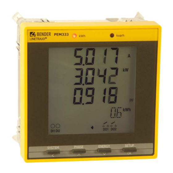
Page 18: Front View
Device description 3.6 Front view Abb. 3.2: Front view PEM330/PEM333 3.7 Connecting terminals The connecting terminals are located on the rear. PEM330-333_D00004_01_M_XXEN/08.2015... -
Page 19: Installation And Connection
4. Installation and connection 4.1 Project planning For any questions associated with project planning, please contact Bender: Internet: www.bender-de.com Tel.: +49-6401-807-0 4.2 Safety instructions Only electrically skilled persons are allowed to connect and commission the device. Such persons must have read this manual and understood all instructions re- lating to safety. -
Page 20: Installing The Device
Installation and connection 4.3 Installing the device 4.3.1 Dimension diagrams Abb. 4.1: Dimension diagram PEM33… (front view) Abb. 4.2: Dimension diagram PEM33… (side view) PEM330-333_D00004_01_M_XXEN/08.2015... -
Page 21: Front Panel Mounting
Installation and connection Abb. 4.3: Dimension diagram PEM33x (panel cut-out) 4.3.2 Front panel mounting A front panel cutout of 92 mm x 92 mm is required for the device. 1. Fit the device through the cut-out in the front panel. 2. -
Page 22: Back-Up Fuses
Installation and connection 4.4.2 Back-up fuses Back-up fuse supply voltage: 6 A Short-circuit protection Protect the measuring inputs according to the re- quirements of the standards. A suitable separator must be provided in order to switch off the power. For details refer to the operating manuals of the measuring current transformers currently used. -
Page 23: Pem330
Installation and connection 4.6.1 PEM330 A2/- A1/+ • l11 l12 • l21 • l31 l32 L1 L2 Abb. 4.4: Wiring diagram PEM330 Legend to wiring diagram PEM330 Not connected Supply voltage. Power protection by a 6 A fuse, quick response. If being supplied from an IT system, both lines have to be protected by a fuse. -
Page 24: Pem333
Installation and connection 4.6.2 PEM333 P1(RS-485) DI1 DI2 D- SH • l11 l12 • l21 • l31 l32 L1 L2 DO13 DO14 DO23 DO24 Abb. 4.5: Wiring diagram PEM333 Legend to wiring diagram PEM333 Connection RS-485 bus Supply voltage. Power protection by a 6 A fuse, quick response. If being supplied from an IT system, both lines have to be protected by a fuse. - Page 25 Installation and connection Digital outputs PEM333 The universal measuring device PEM333 features 2 configurable outputs (N/O contacts). DO13 DO14 DO23 DO24 Abb. 4.6: Digital outputs PEM333 Rated operational AC 230 V DC 24 V AC 110 V DC 12 V voltage Rated operational current...
-
Page 26: Pem333-P
Installation and connection 4.6.3 PEM333-P kvarh P1 (RS-485) A2/- A1/+ kWh+ kWh- • l11 • l21 • l31 kvarh+ kvarh- Abb. 4.8: Wiring diagram Legend to wiring diagram Connection RS-485 bus Supply voltage. Power protection by a 6 A fuse, quick response. If being supplied from an IT system, both lines have to be protected by a fuse. - Page 27 Installation and connection Pulse outputs PEM333-P (internal connection diagram) PEM333-P DO1...2 Abb. 4.9: Pulse outputs PEM333-P (internal connection diagram)) Digital inputs PEM333-P The universal measuring device PEM333-P provides 2 digital inputs. The in- puts are supplied by a galvanically isolated DC 24 V voltage. Through an exter- nal wiring a current of at least I >...
-
Page 28: Connection Diagram Voltage Inputs
Installation and connection 4.7 Connection diagram voltage inputs 4.7.1 Three-phase 4-wire system (TN, TT, IT systems) The PEM can be used in three-phase 4-wire systems, independent of the type of distribution system (TN, TT, IT system). AC 400 V / 230 V Abb. -
Page 29: Three-Phase 3-Wire System
Installation and connection 4.7.2 Three-phase 3-wire system The PEM can be used in three-phase 3-wire systems. The line-to-line voltage must not exceed AC 400 V. For usage in three-wire systems, the connection type (TYPE) has to be set to delta (DELTA) (see page 51). For this purpose, the measurement inputs L2 and N are to be bridged. -
Page 30: One-Phase 3-Wire System (1P3W)
Installation and connection 4.7.3 One-phase 3-wire system (1P3W) Abb. 4.13: Connection diagram one-phase 3-wire system 4.7.4 One-phase 2-wire system (1P2W) AC 230 V Abb. 4.14: Connection diagram one-phase 2-wire system PEM330-333_D00004_01_M_XXEN/08.2015... -
Page 31: Connection Via Voltage Transformers
Installation and connection 4.7.5 Connection via voltage transformers The coupling via measuring voltage transformers allows the use of a measuring device in medium and high voltage systems. The transformation ratio in PEM330/PEM333 can be adjusted (1…2200). LV / MV / HV Abb. - Page 32 Installation and connection PEM330-333_D00004_01_M_XXEN/08.2015...
-
Page 33: Commissioning
5. Commissioning 5.1 Check proper connection During installation and connection, abide by the relevant standards and regulations and follow the operating manuals for the device. 5.2 Before switching on Before switching on think carefully about these questions: 1. Does the connected supply voltage U correspond to the nameplates information? 2. -
Page 34: System Integration And Visualisation
Modbus-RTU. For details refer to Chapter 8. Modbus Register Map and to the internet www.modbus.org. In addition, it can be incorporated into Bender's own BMS (Bender measuring device interface) bus protocol via additional communication modules. This al- lows communication with Bender devices (already existing) to realise device parameter setting and visualisation of measuring values and alarms. -
Page 35: Operation
6. Operation 6.1 Getting to know the operating elements Abb. 6.1: Operating elements Legend to operating elements Element Description LED "kWh" Pulse output, see "Chapter 6.5 LED indication", page 41 LED "kvarh" LC display Display mean value and total value (current, voltage) "SYSTEM"... -
Page 36: Lc Display Test
Operation Display measured values: Active and reactive energy "ENERGY" import/active and reactive energy export (line 4) button in the menu: move down one entry in case of numerical values: reduce the value Press > 3 s: switching between setup menu and stan- "SETUP"... -
Page 37: Getting To Know Standard Display Indications
Operation 6.3 Getting to know standard display indications The display is divided into five areas. Abb. 6.3: Display areas Legend to the display areas Measured values Measurement units Displays the indicators for digital inputs and outputs (DI status, DO status), total harmonic distortion THD, unbalance (unb), quadrant (see page 38) Displays energy information such as active energy import and export and reactive energy import and export and apparent energy... - Page 38 Operation Description of the default display screens (segments 3-5 ) Area Segments Symbol description DI open DO open DI closed DO closed Total harmonic distor- Unbalance tion Quadrant Alarm symbol Indicator apparent Export indicator (active energy and reactive energy) PEM330-333_D00004_01_M_XXEN/08.2015...
- Page 39 Operation Area Segments Symbol description Phase voltage Line-to-line voltage Neutral current Voltage-/cur- rent‐unbalance Demand Total harmonic Total harmonic Displacement distortion distortion I 1/2/3 factor (THD) (THD) L1/L2/L3 Phase angle Phase angle k-factor L1/L2/L3 1/2/3 Tab. 6.1: Standard display indications PEM330-333_D00004_01_M_XXEN/08.2015...
-
Page 40: Power And Current Demand (Demand Display)
Operation 6.4 Power and current demand (Demand display) The demands are indicated on the display according to the following scheme: Abb. 6.4: Display: peak demand Demand displays: Active power demand P Reactive power demand Q Apparent power demand S Peak demand value PEM330-333_D00004_01_M_XXEN/08.2015... -
Page 41: Led Indication
Operation 6.5 LED indication The universal measuring device features two red LEDs on its front panel: "kWh" and "kvarh". The two LED indicators are used for the indication of kWh and kvar, if the EN PULSE function is enabled. The setting can be carried out in the setup menu using the buttons on the front or via the communication interface (PEM333 only). -
Page 42: Data Display For Wye Or Delta Connection
Operation 6.7 Data display for wye or delta connection There are three buttons that are used to indicate the measured data: "SYS- TEM", "PHASE" and "ENERGY". The following tables illustrate how to retrieve individual values for wye or delta connection (setup menu point TYPE, register 41012). -
Page 43: Phase" Button
Operation Column Column left First line Second line Third line right kvar Demand P Demand Q Demand S Tab. 6.2: Data display screens via "SYSTEM" button Comment: In "delta connection" mode the display shows "– " 6.7.2 "PHASE" button Column Column First line Second line... - Page 44 Operation Column Column First line Second line Third line left right λ λ λ Displacement Displacement Displacement factor cos (φ) factor cos (φ) factor cos (φ) THD U THD U THD U THD I THD I THD I k-factor I k-factor I k-factor I Phase angle U...
-
Page 45: Energy" Button
Operation 6.7.3 "ENERGY" button Parameters in the fourth line: Column left Column right Value Active energy import Active energy export kvarh Reactive energy import kvarh Reactive energy export Apparent energy Tab. 6.4: Display screens via "ENERGY" button 6.8 Data display for one-phase connections There are three buttons that are used to indicate the measured data: "SYS- TEM", "PHASE"... - Page 46 Operation Column Column left First line Second line Third line right Demand I Demand I kvar Demand P Demand Q Demand S Tab. 6.5: Data display screens via "SYSTEM" button Comment: * for 1P2W: display „--“ PEM330-333_D00004_01_M_XXEN/08.2015...
-
Page 47: Button „Phase
Operation 6.8.2 Button „PHASE“ Column Column First line Second line Third line left right L1L2* λ λ Displacement Displacement factor cos (φ) factor cos (φ) THD U THD U PEM330-333_D00004_01_M_XXEN/08.2015... -
Page 48: Button „Energy
Operation Column Column First line Second line Third line left right THD I THD I k-factor I k-factor I Phase angle U Phase angle U Phase angle I Phase angle I Tab. 6.6: Display screens via "PHASE" button * not for 1P2W 6.8.3 Button „ENERGY“... -
Page 49: Setup Using The "Setup" Button
Operation 6.9 Setup using the "SETUP" button Press the "SETUP" button for more than 3 s to access the setup mode. Press the "SETUP" button again to return to the default display screen. To be able to change parameters, you must first enter the password. -
Page 50: Setup: Overview Diagram Menu
Operation 6.9.2 SETUP: Overview diagram menu The following diagram will help you to familiarise yourself with the menu: Serial number of device info INFO Date of software update UPDATE Protocol version PRO VER set backlight time out BLTO SET Software Version SW-VER choose CT direction CT REV... -
Page 51: Setup: Setting Possibilities
Operation 6.10 Setup: Setting possibilities The table represents the messages indicated on the display, their meaning and their setting possibilities. Display entry Setting Factory Level 1 Parameters Description options setting Level 2 PROGRAM- Setup mode MING PASSWORD Password Enter password SET PASS Change pass- YES/NO... - Page 52 Operation Display entry Setting Factory Level 1 Parameters Description options setting Level 2 Baud Baud rate Set baud rate 1200/2400/ 9600 4800/9600/ 19200 bps CONFIG Comm. port Configuration 8N2/8O1/8E1/ configura- parity bit 8N1/8O2/8E2 tion DATE Date Setting the date YY-MM-DD Time Setting the time HH:MM:SS...
- Page 53 Operation Display entry Setting Factory Level 1 Parameters Description options setting Level 2 PERIOD Measuring Specify the time 1, 2, 3, 5, 10, time of defi- for demand mea- 15, 30, 60 ned length surement (minutes) NUM Number of Set the number of 1…15 sliding sliding...
- Page 54 Operation Display entry Setting Factory Level 1 Parameters Description options setting Level 2 I1 REV I Change CT YES/NO polarity I2 REV I I2 Change CT YES/NO polarity I3 REV I Change CT YES/NO polarity BLTO SET Display ligh- Time duration 0…59 ting until the display...
- Page 55 Operation Comments on the table above * There are various types of calculating the apparent power S: Vector method V: Scalar method S: The calculation method can be selected: V = vector method S = scalar method ** PEM33x-251 only PEM330-333_D00004_01_M_XXEN/08.2015...
- Page 56 Operation λ Power factor conventions Reactive power import Quadrant 2 Quadrant 1 Power factor (-) Power factor (+) Active power export (-) Active power import (+) Reactive power import (+) Reactive power import (+) Active power import Quadrant 3 Quadrant 4 Power factor (-) Power factor (+) Active power export (-)
- Page 57 Operation Select transformer ratio for the current transformer Example: CT 1000 : 5 (= 200) Button Display entry Description SETUP > 3 s PROGRAMMING PASSWORD **** PASSWORD 0 0 flashes PASSWORD 0 (or Password) SET PASS NO TYPE WYE PT 1 CT 1 CT 1 1 flashes...
- Page 58 Operation PEM330-333_D00004_01_M_XXEN/08.2015...
-
Page 59: Application/Inputs And Outputs
7. Application/inputs and outputs 7.1 Digital inputs (PEM333… only) The device features two digital inputs that are internally operated with DC 24 V. Digital inputs are typically used for monitoring external states. The switching states of the digital inputs can be read from the LC display or from connected system components. -
Page 60: Digital Pulse Outputs (Pem333-P Only)
Application/inputs and outputs In order to determine the actual amount of energy, the flashing frequency can be calculated from the CT ratio and the pulse constant.. Comment: Pulse constant VT = voltage Pulses per kWh transformer ratio VT x ratio CT CT = current transformer ratio VT x ratio CT... -
Page 61: Demand Dmd
Application/inputs and outputs 7.5.3 Demand DMD Demand is defined as the approximate average power consumption over a fixed interval. The following values are determined: Active power P Apparent power S Reactive power Q ... - Page 62 Application/inputs and outputs The following settings are possible: Setpoint type Parameters Values exceeded Phase voltages U (x100 V) Line-to-line voltages U (x100 V) I (x1000 A) (x1000 kW) (x1000 kvar) Value below limit Phase voltages U (x100 V) Line-to-line voltages U (x100 V) Power factor λ...
-
Page 63: Event Log (Soe Log)
Application/inputs and outputs 7.7 Event log (SOE log) The device can store up to 32 events. If there are more than 32 events, the newest event will replace the oldest event on a first-in-first-out basis: The 33 event overwrites the first entry, the 34 the second etc. -
Page 64: Unbalance
Application/inputs and outputs 7.8.2 Unbalance The device can measure voltage and current unbalance. The following calculation method is applied: – Ø U|,|U – Ø U|,|U – Ø U|] Voltage x100 % unbalance Ø U – Ø I|,|I – Ø I|,|I –... -
Page 65: Modbus Register Map
8. Modbus Register Map This chapter provides a complete description of the Modbus register map (protocol version 6.0) for the PEM330/PEM333 series, to facilitate accessing in- formation. In general, the registers are implemented as Modbus Read Only Registers (RO = read only) with the exception of the DO control registers, which are implemented as Write Only Registers (WO = write only). -
Page 66: Basic Measuring Values
Modbus Register Map 8.1 Basic measuring values Scale/ Register Property Description Format unit 40000 UINT32 ×100 V 40002 UINT32 ×100 V 40004 UINT32 ×100 V Ø U 40006 UINT32 ×100 V 40008 UINT32 ×100 V L1L2 40010 UINT32 ×100 V L2L3 40012 UINT32... - Page 67 Modbus Register Map Scale/ Register Property Description Format unit 40030 INT32 ×1000 kW 40032 INT32 ×1000 kvar 40034 INT32 ×1000 kvar 40036 INT32 ×1000 kvar 40038 INT32 ×1000 kvar 40040 INT32 ×1000 kVA 40042 INT32 ×1000 kVA 40044 INT32 ×1000 kVA 40046 INT32 ×1000 kVA...
- Page 68 Modbus Register Map Scale/ Register Property Description Format unit 40055 Voltage unbalance UINT16 x1000 40056 Current unbalance UINT16 x1000 Displacement factor 40057 INT16 x1000 Displacement factor 40058 INT16 x1000 Displacement factor 40059 INT16 x1000 40060 Demand P INT32 x1000 kW 40062 Demand Q INT32...
- Page 69 Modbus Register Map Scale/ Register Property Description Format unit Phase angle I 40076 UINT16 x100 ° Phase angle I 40077 UINT16 x100 ° 40078… Reserved 40094 40095 Bitmap Alarm Status digital 40096 Bitmap outputs Status digital 40097 Bitmap inputs 40098 UNIT32 SOE pointer Tab.
- Page 70 Modbus Register Map The alarm register 40095 shows various alarm states (1 = active, 0 = inactive). The table illustrates details of the alarm register. Bit in register 40095 Alarm by event B0…B2 Reserved Setpoint 1 Setpoint 2 Setpoint 3 Setpoint 4 Setpoint 5 Setpoint 6...
-
Page 71: Energy Measurement
Modbus Register Map 8.2 Energy measurement Register Characteristics Description Format Unit 40100 Active energy UINT32 x0.1 kWh import 40102 Active energy UINT32 x0.1 kWh export 40104 Reserved 40106 Reactive UINT32 x0.1 kvarh energy import 40108 Reactive UINT32 x0.1 kvarh energy export 40110 Reserved 40112... -
Page 72: Energy Measurement Per Phase
Modbus Register Map 8.3 Energy measurement per phase Charac- Register Description Format Unit teristics 40200 Import active energy L1 UINT32 x0.1 kWh 40202 Export active energy L1 x0.1 kWh 40204 Reserved 40206 Reserved 40208 Import reactive energy L1 x0.1 kvarh 40210 Export reactive energy L1 x0.1 kvarh... - Page 73 Modbus Register Map Charac- Register Description Format Unit teristics 40232 Reserved 40234 Apparent energy L2 UINT32 x0.1 kVAh 40236 Import active energy L3 UINT32 x0.1 kWh 40238 Export active energy L3 x0.1 kWh 40240 Reserved 40242 Reserved 40244 Import reactive energy L3 x0.1 kvarh 40246 Export reactive energy L3...
-
Page 74: Peak Demand
Modbus Register Map 8.4 Peak demand The value of the peak demand register is 1000 times the actual value, that means, that the value of the register has to be divided by 1000 to obtain the value in kW, kVA or kvar. Register Characteristics Description... -
Page 75: Total Harmonic Distortion (Thd) And K-Factor
Modbus Register Map Total harmonic distortion (THD) and k-factor Total harmonic distortion (THD): The value of the THD returned is 10,000 times the actual value. Example: If the register contains a value of 1031, it means 1031/10.000 = 0.1031 or 10.31 % k-factor: The value of the k-factor that is returned is ten times the actual meas- ured value. -
Page 76: Connection Fault Detection
Modbus Register Map 8.6 Connection fault detection The universal measuring device not only detects connection faults but also di- agnoses the fault type. Register Property Description Format 40900 Connection fault detection UINT16 The diagnosis bit indicates the type of connection fault. If the bit value is = 1, a fault has been detected. - Page 77 Modbus Register Map Event Polarity measuring current transformer I interchanged? Polarity measuring current transformer I interchanged? Polarity measuring current transformer I interchanged? Reserved Reserved Tab. 8.8: Details diagnosis bit "Connection fault detection" Comments: If B01 is set to 1, the fault detection cannot be carried out. If the two bits B02 and B03 are set to 1, the fault detection cannot be carried out.
-
Page 78: Setup Parameters
Modbus Register Map 8.7 Setup parameters Register Property Description Format Range/unit 41000…41006 Reserved 41007 activate "ARM UINT16 0 = deactivated before EXECUTING" 1* = activated 41010 Transformer ratio UINT16 1…2200 voltage transformer (100 41011 Transformer ratio UINT16 1…6000 measuring current (current input 5 A) transformer 1…30000... - Page 79 Modbus Register Map Register Property Description Format Range/unit 41016… Reserved 41018 41019 clear all energy UINT16 Writing 0xFF00 to value registers the register clears the values for P, Q and S 41020 Resets the event UINT16 Writing 0xFF00 to the register resets the SOE pointer of the event log to 0 41021…...
- Page 80 Modbus Register Map Register Property Description Format Range/unit 41054 Calculation method UINT16 B1B0: 00* = vector 01 = scalar 41055 Reserved 41056 Polarity measuring UINT16 0* = normal current transfor- 1 = reversed mer L1 41057 Polarity measuring UINT16 0* = normal current transfor- 1= reversed mer L2...
- Page 81 Modbus Register Map Register Property Description Format Range/unit 41227 Reset Max/Min log UINT Writing „0xFF00“ to the register resets the Max/ Min log to 0 Tab. 8.9: Setup parameters Data structure setpoint The internal data structure of the 4 registers belonging to each setpoint is de- scribed in the table below.
- Page 82 Modbus Register Map λ The value of the power factor displayed is 1000 times the measured value. Example: desired setpoint is 0.866; value to be set: 0.866 x1000 = 866. (x100 V) (x100 V) (x1000 A) (x1000 kW) (x1000 kvar) power factor λ...
-
Page 83: Event Log (Soe Log)
Modbus Register Map 8.8 Event log (SOE log) Each SOE event occupies 7 registers, as shown in the following table. The in- ternal data structure of the event log is listed in table 8.12. Register Characteristics Description Format 42000…42006 Event 1 see table 8.12 42007…42013 Event 2... - Page 84 Modbus Register Map Event data structure The internal data structure of the 7 registers belonging to each event in the SOE log is described in the table below. Register Characteristics Description Register 1 Reserved Register 2 Event classification (see table 8.13 on page 86) Register 3 Event value HiWord Register 4...
- Page 85 Modbus Register Map Event classification Event Meaning classification Digital input 1 closed Digital input 1 open Digital input 2 closed Digital input 2 open 5…10 Reserved Digital output 1 closed Digital output 1 open Digital output 2 closed Digital output 2 open 15…21 Reserved Failure supply voltage...
- Page 86 Modbus Register Map Event Meaning classification Setpoint active: line-to-line voltage exceeded Setpoint active: I exceeded Setpoint active: P exceeded Setpoint active: Q exceeded Setpoint active: phase voltage exceeded Setpoint active: line-to-line voltage below setpoint Setpoint active: power factor below setpoint Setpoint inactive: phase voltage exceeded Setpoint inactive: line-to-line voltage exceeded Setpoint inactive: I exceeded...
-
Page 87: Max/Min Log
Modbus Register Map 8.9 Max/Min Log 8.9.1 Maximum values Register Property Description Format Range/unit 43000 x100 V L1 max 43004 x100 V L2 max 43408 x100 V L3 max 43012 Ø U x100 V LN max 43016 x100 V L1L2 max 43020 x100 V L2L3 max... - Page 88 Modbus Register Map Register Property Description Format Range/unit 43052 x1000 kW L2 max 43056 x1000 kW L3 max 43060 x1000 kW ges max 43064 x1000 kvar L1 max 43068 x1000 kvar L2 max 43072 x1000 kvar L3 max 43076 x1000 kvar ges max 43080 x1000 kVA...
- Page 89 Modbus Register Map Register Property Description Format Range/unit 43112 x100 Hz 43116 max. x1000 voltage unbalance 43120 max. x1000 current unbalance 43124 x10.000 UL1 max see table 8.16 43128 x10.000 UL2 max 43132 x10.000 UL3 max 43136 x10.000 I1 max 43140 x10.000 I2 max...
-
Page 90: Minimum Values
Modbus Register Map 8.9.2 Minimum values Register Property Description Format Range/unit 43200 x100 V L1 min 43204 x100 V L2 min 43208 x100 V L3 min 43212 Ø U x100 V LN min 43216 x100 V L1L2 min 43220 x100 V L2L3 min 43224 x100 V... - Page 91 Modbus Register Map Register Property Description Format Range/unit 43256 x1000 kW L3 min 43260 x1000 kW ges min 43264 x1000 kvar L1 min 43268 x1000 kvar L2 min 43272 x1000 kvar L3 min 43276 x1000 kvar ges min 43280 x1000 kVA see table 8.16 L1 min 43284...
- Page 92 Modbus Register Map Register Property Description Format Range/unit λ 43308 x1000 ges min 43312 x100 Hz 43316 min. unbalance U x1000 43320 min. unbalance I x1000 43324 x10.000 UL1 min see table 8.16 43328 x10.000 UL2 min 43332 x10.000 UL3 min 43336 x10.000 I1 min...
-
Page 93: Data Structure Max/Min Log
Modbus Register Map 8.9.3 Data structure Max/Min log Offset Property Description Format HiWord: max. resp. min UINT16 value LoWord: max. resp. min UINT16 value HiWord: UNIX time UINT16 LoWord: UNIX time UINT16 Tab. 8.16: Data structure Max/Min log PEM330-333_D00004_01_M_XXEN/08.2015... -
Page 94: Time Setting
Modbus Register Map 8.10 Time setting The PEM333… provides two time display formats: 1. Year/Month/Day/Hour/Minute/Second register 60000…60002 2. UNIX time register 60004…60005 When sending the time via Modbus communications, make sure to use only one time display format of the two time register sets. All registers within a time register set must be written in a single transaction. -
Page 95: Dox Control
Modbus Register Map 8.11 DOx control The DI control register are implemented as "Write-Only" registers (WO) and are set with the function code 0x05. In order to query the current DO status, the register 40066 has to read out. PEM executes commands to the outputs in two steps (ARM before EXECUT- ING): Before sending an open or close command to one of the outputs, it must be activated first. -
Page 96: Universal Measuring Device Information
Modbus Register Map 8.12 Universal measuring device information Register Property Description Format Comment see "Chapter Tab. 60200… 60219 UINT16 8.20: ASCII coding of Model "PEM333"" 60220 Software version UINT16 e.g.: 10000 = V1.00.00 60221 Protocol version UINT16 e.g.: 40 = V4.0 60222 Software update date UINT16 e.g.: 080709 =... - Page 97 Modbus Register Map A coding example is given in the table below using the "PEM333" by way of example. Register Value (Hex) ASCII 60200 0x50 60201 0x45 60202 0x4D 60203 0x33 60204 0x33 60205 0x33 60206…60219 0x20 Null Tab. 8.20: ASCII coding of "PEM333" PEM330-333_D00004_01_M_XXEN/08.2015...
- Page 98 Modbus Register Map PEM330-333_D00004_01_M_XXEN/08.2015...
-
Page 99: Technical Data
9. Technical data Insulation co-ordination Measuring circuit Rated insulation voltage............................300 V Overvoltage category..............................III Pollution degree................................2 Supply circuit Rated insulation voltage............................300 V Overvoltage category..............................II Pollution degree................................2 Supply voltage Rated supply voltage ..........................95…250 V Frequency range of .........................DC, 44…440 Hz Power consumption .............................≤... - Page 100 Technical data Accuracies (of measured value/of full scale value) Phase voltage ..................± 0.2 % of measured value L1-N L2-N L3-N Current ..................± 0.2 % of measured value + 0.05 % of full scale value Neutral current ..........................1 % of full scale value Frequency.................................±...
- Page 101 Technical data Environment/EMC EMC ..............................IEC 61326-1, table 2 Operating temperature ..........................-25…+55 °C Climatic class acc. to DIN EN 60721 Stationary use ................................3K5 Classification of mechanical conditions acc. to DIN EN 60721 Stationary use ................................3M4 Connection Connection.............................screw-type terminals Other Degree of protection, installation ..........................IP20 Degree of protection, front ............................IP52 Flammability class .............................
-
Page 102: Standards And Certifications
Technical data 9.1 Standards and certifications PEM330/PEM333… was designed under consideration of the following standards: DIN EN 62053-22 (VDE 0418 Part 3-22) Electricity meter equipment (AC) - Particular requirements - Part 22: Static meters for active energy (classes 0,2 S and 0,5 S (IEC 62053); DIN EN 61557-12 (VDE 0413-12) Electrical safety in low voltage distribution systems up to AC 1 000 V and DC 1 500 V –... -
Page 103: Index
INDEX "ENERGY" button 45 Dimension diagram 20 "PHASE" button 43 Display mode "SYSTEM" button 42 - Data display 42 - Standard display 41 Apparent power, calculation 55 Area of application 13 Energy Pulsing - LED indication 41 Energy pulsing Back-up fuses 22 - activate/deactivate 53 - Display 59 Event... - Page 104 Installation 19 Intended use 11 Phase angle - Current 60 - Voltage 60 k-factor 44 Power factor rules 56 k-Faktor 48 Power Quality 63 LC display Safety instructions 12 - Power and current demands 40 SERVICE 8 – - Standard display indications 37 Set demand period 61 Setpoint - TEST 36...
- Page 105 Unbalance 64 Versions 15 Wiring diagram 22 Work activities on electrical installations 11 workshops 9 PEM330-333_D00004_01_M_XXEN/08.2015...
- Page 108 Bender GmbH & Co. KG Londorfer Str. 65 • 35305 Gruenberg • Germany Postfach 1161 • 35301 Gruenberg • Germany Tel.: +49 6401 807-0 Fax: +49 6401 807-259 Email: info@bender.de www.bender.de Photos: Bender archives...
Need help?
Do you have a question about the LINETRAXX PEM330 and is the answer not in the manual?
Questions and answers