
Subscribe to Our Youtube Channel
Related Manuals for Bender PEM735


Summary of Contents for Bender PEM735
- Page 1 Manual PEM735 Measuring case Measuring and demonstration case PEM735-measuring_case_D00240_00_M_XXEN/12.2015 B 9830 0014...
- Page 2 Bender GmbH & Co. KG P. O. Box 1161 • 35301 Gruenberg • Germany Londorfer Str. 65 • 35305 Gruenberg • Germany Tel.: +49 6401 807-0 © Fax: +49 6401 807-259 Bender GmbH & Co. KG E-Mail: info@bender.de All rights reserved.
-
Page 3: Table Of Contents
Application of the Rogowski coils ............. 12 4.1.1 Settings on the case ..................13 4.1.2 Mounting Rogowski coils ................14 4.1.3 Settings on the PEM735 ................14 Application of AUX transformers ............... 15 4.2.1 Settings on the case ..................16 4.2.2 Mounting AUX transformers ............... 16 4.2.3... - Page 4 Table of Contents 8. Technical data ..................21 9. Ordering information ................23 INDEX ......................25 PEM735-measuring_case_D00240_00_M_XXEN/12.2015...
-
Page 5: Function And Safety
Function and safety 1. Function and safety The PEM735 measuring and demonstration case is used for mobile measurements to analyse the voltage quality accord- ing to DIN EN 50160 (measurement according to IEC 61000- 4-30 class A). For the use of this measuring case, specialist knowledge is required. -
Page 6: Content Of The Measuring Case
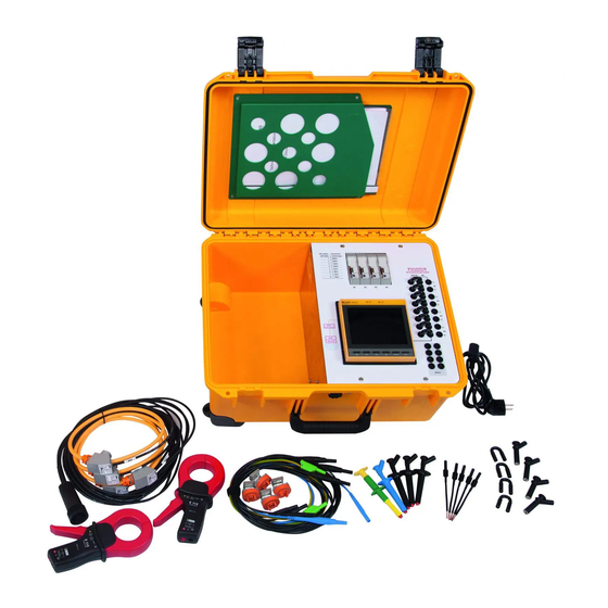
Content of the measuring case 2. Content of the measuring case Universal measuring device PEM735 (IP address 192.168.0.10) Integrated WLAN router (IP address 192.168.0.254; admin/admin) 4 flexible Rogowski coils and transducers for current measurement 100…4000 A ... -
Page 7: Connecting The Measuring Case
Rogowski coils) 2. Install measuring current transformer 3. Commission measuring case 4. Configure PEM735 5. Install measuring voltage cables The measuring case is operated with 230 V, 50 Hz. The connecting cable is included. PEM735-measuring_case_D00240_00_M_XXEN/12.2015... -
Page 8: Front Plate
Connecting the measuring case 3.1 Front plate The case contains the PEM735 connected to the front plate, a router, the transducers for the Rogowski coils and the jumper wires to configure the transformers being used. Rogowski W1 W2 W3 W4... -
Page 9: Wiring Panel Side
Power supply of the measuring case Voltage transformer inputs Measuring current transformer inputs Network connection input Digital inputs Relay outputs Ethernet RO24 RO23 RO14 RO13 Rogowski Fig. 3.2: Wiring panel side PEM735-measuring_case_D00240_00_M_XXEN/12.2015... - Page 10 Connecting the measuring case Legend wiring panel side Description On/off switch of the measuring case Measuring voltage inputs Power supply socket for measuring case Ethernet connection socket Measuring current transformer inputs Digital inputs and relay outputs Connection Rogowski coils PEM735-measuring_case_D00240_00_M_XXEN/12.2015...
-
Page 11: Current Measurement
Current measurement 4. Current measurement The universal measuring device PEM735 integrated in the measuring case is set to the "load meter arrow system". When installing the transformers, make sure that the imprinted direction arrows point at the load. Otherwise you will receive incorrect measurement values. -
Page 12: Application Of The Rogowski Coils
For easier assignment of the measurement values, the Rogowski coils are labelled (5A1…4). Fig. 4.2: Rogowski coil Legend Rogowski coil Description Plug of the 4 Rogowski coils Coil enclosure Bayonet connection Measuring coil (orange) Signal cable (black) Mounting aid for busbar measurement PEM735-measuring_case_D00240_00_M_XXEN/12.2015... -
Page 13: Settings On The Case
Table 4.1: Table DIP switches for transducers For "Compensation", the length of the used Rogowski coil is indicated in mm. The sup- plied Rogowski coils must be set to 600. 3. All 8 jumper wires must be inserted in Rogowski position "Rogowski". PEM735-measuring_case_D00240_00_M_XXEN/12.2015... -
Page 14: Mounting Rogowski Coils
If necessary, you can adjust the enclosure position clockwise in 15° steps. Disassemble in reverse order. 4.1.3 Settings on the PEM735 1. Commissioning measuring case with mains plug. 2. Set primary current to measuring range (Settings / Basic / CT Primary) 3. -
Page 15: Application Of Aux Transformers
Rogowski Example: Application of 3 AUX transformers. AUX4 not in use, therefore short-circuited When using your own measuring current transformers, be aware that the secondary current may have a maximum of 5 A! PEM735-measuring_case_D00240_00_M_XXEN/12.2015... -
Page 16: Settings On The Case
5 kHz max. 1 kHz red measuring cable socket X1 black measuring cable socket X2 4.2.3 Settings PEM735 C112 Primary current 1000 A (Settings / Basic / CT Primary) Secondary current 1 A (Settings / Basic / CT Secondary) -
Page 17: Use Of 3 Rogowski Coils And 1 Aux Transformer
Mounting transformer W1…3: Intall the three Rogowski coils 5A1…3 (refer to chapter 4.1.2). Install the AUX transformer (refer to chapter 4.2.2). 4.3.3 Settings PEM735 Primary current W1…3 as measuring range (Settings / Basic / CT Primary) Secondary current W1…3 1 A (Settings / Basic / CT Secondary) -
Page 18: Voltage Measurement
To connect the secured side of the measuring voltage cable you have the following op- tions: Crocodile clips (PE always, for other cables optional) Safety crocodile clips for use with push-wire terminals Magnetic test probes to enable the screws to make contact with the circuit breaker PEM735-measuring_case_D00240_00_M_XXEN/12.2015... -
Page 19: Digital Inputs And Relay Outputs
Fig. 6.1: Digital inputs 6.2 Relay outputs RO1…2 The measuring case features two relay outputs. . Rated operational AC 230 V DC 24 V AC 110 V DC 12 V RO13 RO14 voltage RO23 RO24 Rated operational current Table 6.1: Relay outputs PEM735-measuring_case_D00240_00_M_XXEN/12.2015... -
Page 20: Network
PEM735. Ethernet address PEM735: IP 192.168.0.10 WLAN: IP 192.168.0.254 (admin/admin) For seamless communication it is important that the PEM735 and the router are in the same network. Default setting: Access point ... - Page 21 Current ........................± 0.1 % mv + 0.05 % fs Frequency ..........................± 0.005 Hz Phasing ...............................± 1 ° Measurement of the active energy ........ acc. to DIN EN 62053-22 (VDE 0418 Part 3-22) Measurement of the voltage r.m.s. values....................................acc. to DIN EN 61557-12 (VDE 0413-12), chapter 4.7.6 PEM735-measuring_case_D00240_00_M_XXEN/12.2015...
- Page 22 ..............................DC 24 V Environment/EMC Operating temperature......................0…+ 40 °C Classification of climatic conditions................. acc. to DIN EN 60721 Height ............................up to 4000 m Other Degree of protection..........................IP20 Dimensions ....................approx. 556 x 416 x 295 mm Weight ............................≤ 16 kg PEM735-measuring_case_D00240_00_M_XXEN/12.2015...
- Page 23 Ordering information 9. Ordering information Type Art. no. PEM735 Measuring case B 9830 0014 PEM735-measuring_case_D00240_00_M_XXEN/12.2015...
- Page 24 Ordering information PEM735-measuring_case_D00240_00_M_XXEN/12.2015...
- Page 25 Digital inputs 9 DIP switch 13 Direction arrows 11 Front plate 8 Measuring coil 12 Measuring current transformer inputs 9 Mounting aid 12 Mounting Rogowski coils busbars 14 Mounting Rogowski coils power supply line 14 Network 20 Network connection 9 PEM735-measuring_case_D00240_00_M_XXEN/12.2015...
- Page 26 INDEX PEM735-measuring_case_D00240_00_M_XXEN/12.2015...
- Page 28 Bender GmbH & Co. KG P. O. Box 1161 • 35301 Gruenberg • Germany Londorfer Str. 65 • 35305 Gruenberg • Germany Tel.: +49 6401 807-0 Fax: +49 6401 807-259 E-Mail: info@bender.de www.bender.de Photos: Bender archives...
Need help?
Do you have a question about the PEM735 and is the answer not in the manual?
Questions and answers