Sign In
Upload
Download
Table of Contents
Contents
Add to my manuals
Delete from my manuals
Share
URL of this page:
HTML Link:
Bookmark this page
Add
Manual will be automatically added to "My Manuals"
Print this page
×
Bookmark added
×
Added to my manuals
Manuals
Brands
Bender Manuals
Measuring Instruments
EDS309 Series
Manual
Bender EDS309 Series Manual
Hide thumbs
1
2
Table Of Contents
3
4
5
6
7
8
9
10
11
12
13
14
15
16
17
18
19
20
21
22
23
24
25
26
27
28
29
30
31
32
33
34
35
36
37
38
39
40
41
42
43
44
45
46
47
48
49
50
51
52
53
54
55
56
57
58
59
60
61
62
63
64
65
66
67
68
69
70
71
72
73
74
75
76
page
of
76
Go
/
76
Contents
Table of Contents
Bookmarks
Table of Contents
Table of Contents
Important Information
How to Use this Manual
Technical Support: Service and Support
First Level Support
Repair Service
Field Service
Training Courses
Delivery Conditions
Inspection, Transport and Storage
Warranty and Liability
Disposal
Overview of Chapters
Safety Instructions
General Safety Instructions
Intended Use
Device-Specific Safety Instructions
System Description
System Components
Overview of System Components
Insulation Fault Location Equipment Type List
Accessories
Function of the System Components
Locating Current Injector PGH18
Insulation Fault Locator EDS195PM
Measuring Clamps
Coupling Device AGE185
Operating Principle for Insulation Fault Location (IΔL)
Schematic Diagram EDS System
Test Cycle
Definitions
Currents in the EDS System
Operating Principle for Residual Current Measurement (Iδn)
Considerations Prior to Use
How Does the Equipment for Insulation Fault Location Work
Requirements for Reliable Insulation Fault Location
Reduced Locating Current
Response Sensitivity Characteristics of the EDS195PM
Response Characteristics for Main Circuits in 3AC Systems
Response Characteristics for Main Circuits in AC Systems
Response Characteristics for Main Circuits in DC Systems
Response Characteristics for Control Circuits in AC Systems
Response Characteristics for Control Circuits in DC Systems
Connecting the Locating Current Injector
Disconnecting Insulation Monitoring Device
Locating Current Injector in an Electrically Isolated IT System
Connection to a Live IT System
Connection to a PV System
Operation
Short Description of Insulation Fault Location (EDS Mode)
Commissioning the PGH18
Insulation Fault Location Using EDS195PM
Detailed Description of Insulation Fault Location
Description of a Residual Current Measurement
Displays and Controls on the PGH18
Displays and Controls on the EDS195PM
Operating the EDS195PM
Switching on and off the Device
Changing the Measuring Clamp
Improved Legibility Due to Display Lighting
Changing between Insulation Fault Location IΔL and Residual Current Measurement Iδn Operating Modes
Quickly Checking the Response Values for IΔL and Iδn
Checking Info Menu
Significance of the Display Elements
Standard Displays on the EDS195PM
EDS Measurement (IΔL)
Standard Display if There Is no Cable to be Measured in the Clamp
Standard Display for EDS Measurement (IΔL) with Cable in the Clamp
Standard Display for Measuring Faults or Pauses between Changes in Polarity of the Measuring Pulse
RCM Measurement (Iδn)
Standard Display for RCM Measurement (Iδn) with Cable in the Clamp
Alarms During EDS Measurement or RCM Measurement
Indication of Device and Measuring Errors
Factory Settings EDS195PM (State as Supplied)
Menu Structure
Navigating in the Menu
Menu Item: Settings
Menu Item: System
Menu Item: Harmonics
Menu Item: IΔL Alarms
Menu Item: Iδn Logger
Practical Usage
Insulation Fault Location in a System Without a Permanently Installed EDS System
Insulation Fault Location in a System with a Permanently Installed EDS System
Insulation Fault Location in Diode-Decoupled DC Systems
Usage of the EDS195PM as a Residual Current Meter
Indication of the Harmonics During Residual Current Measurement
Coupling Device AGE185 for Higher System Voltages
Power Supply for the EDS195PM
Displaying Charge State
Changing Batteries
Power Supply Unit Supplied
Technical Specifications
Technical Specifications for the System EDS309
Technical Specifications PGH18
Technical Specifications EDS195PM
Technical Specifications Measuring Clamps
Technical Specifications AGE185
Standards and Certifications
Dimension Diagrams
Status Word
Ordering Data Including Accessories
Component List
Frequently Asked Questions
Additional Fault Location Information Using the Eds309X
Required Equipment
Irdh575B2- 435
Collecting and Analysing Information
Taking Measurements
Index
Advertisement
Quick Links
1
Table of Contents
Download this manual
Manual
EDS3090
...91, ...92, ...96
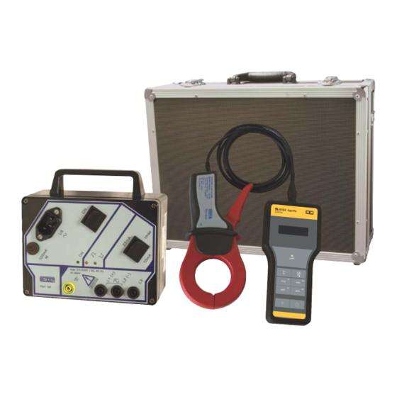
Portable equipment for insulation fault location
for energised and deenergised AC and DC systems
Software version: D399 V2.1
EDS309x_D00012_05_M_XXEN/12.2017
Table of
Contents
Previous
Page
Next
Page
1
2
3
4
5
Advertisement
Table of Contents
Need help?
Do you have a question about the EDS309 Series and is the answer not in the manual?
Ask a question
Questions and answers
Subscribe to Our Youtube Channel
Related Manuals for Bender EDS309 Series
Industrial Electrical Bender ISOSCAN W Series Manual
Insulation fault locator to locate insulation faults in ungrounded dc, ac and three-phase power supplies (88 pages)
Industrial Equipment Bender ISOSCAN EDS44 Series Quick Start Manual
Insulating fault locator (17 pages)
Relays Bender ISOSCAN EDS440 Connection Manual
(16 pages)
Measuring Instruments Bender EDS3090 Manual
Portable equipment for insulation fault location for energised and deenergised ac and dc system (68 pages)
Measuring Instruments Bender EDS3092 Manual
Portable equipment for insulation fault location for energised and deenergised ac and dc system (68 pages)
Measuring Instruments Bender EDS3096 Manual
Portable equipment for insulation fault location for energised and deenergised ac and dc system (68 pages)
Measuring Instruments Bender EDS150 Manual
Insulation fault locator (8 pages)
Measuring Instruments Bender EDS44-CN Series Quick Start Manual
Insulating fault locator (9 pages)
Measuring Instruments Bender EDS44-CN Series Quick Start Manual
Insulating fault locator (8 pages)
Measuring Instruments Bender EDS195PM Manual
(76 pages)
Measuring Instruments Bender COMTRAXX COM465ID Manual
Condition monitor with integrated gateway for the connection of bender isodata devices with ethernet tcp/ip networks (28 pages)
Measuring Instruments Bender A-ISOMETER IRDH275 Operating Manual
Insulation monitoring device for it ac systems with galvanically connected rectifiers and converters and for it dc systems (76 pages)
Measuring Instruments Bender iso685-S Series Commissioning
Devices without a connected display fp200(w) (12 pages)
Measuring Instruments Bender ISOMETER iso685 Series Manual
Insulation monitoring device (17 pages)
Measuring Instruments Bender ISOMETER isoPV425+AGH420 Quick Start Manual
Insulation monitoring device for unearthed dc circuits it systems for photovoltaic systems up to 3 n ac, ac 690 v / dc 1000 v (13 pages)
Measuring Instruments Bender MK2007CBM Manual
Remote alarm indicator and test combination for medically used rooms (9 pages)
This manual is also suitable for:
Pgh18 series
Eds195pm
Eds440
Table of Contents
Print
Rename the bookmark
Delete bookmark?
Delete from my manuals?
Login
Sign In
OR
Sign in with Facebook
Sign in with Google
Upload manual
Upload from disk
Upload from URL


Need help?
Do you have a question about the EDS309 Series and is the answer not in the manual?
Questions and answers