
Related Manuals for Bender PEM533 Series


Summary of Contents for Bender PEM533 Series
- Page 1 Manual PEM533 Universal measuring device Software version 2.00.XX B 9310 0533 B 9310 0534 B 9310 0535 B 9310 0536 PEM533_D00013_01_M_XXEN/01.2016...
- Page 2 Bender GmbH & Co. KG Londorfer Str. 65 • 35305 Gruenberg • Germany © Postfach 1161 • 35301 Gruenberg • Germany Bender GmbH & Co. KG Tel.: +49 6401 807-0 All rights reserved. Fax: +49 6401 807-259 Reprinting only with permission E-Mail: info@bender.de...
-
Page 3: Table Of Contents
Table of Contents 1. Making effective use of this document ..........7 How to use this manual ..................7 Technical support: Service and support ............8 Workshops ......................... 9 Delivery conditions, guarantee, warranty and liability ......10 2. Safety ...................... 11 Intended use ...................... - Page 4 Table of Contents Instructions for connection ................19 Wiring diagram ....................... 20 Connection diagram voltage inputs ............... 21 4.7.1 Three-phase 4-wire systems (TN, TT, IT systems) ......21 4.7.2 Three-phase 3-wire system ............... 21 4.7.3 Connection via voltage transformers ........... 22 Digital inputs ......................
- Page 5 Table of Contents 7. Application/inputs and outputs ............45 Digital inputs ......................45 Digital outputs ......................45 Display Energy pulsing ..................45 Power and energy ....................45 7.4.1 Voltage and current phase angles ............45 7.4.2 Energy ......................46 7.4.3 Demand DMD ....................
- Page 6 Table of Contents 8.7.4 Min log of last month .................. 73 Setup parameters ....................75 8.8.1 Digital input setpoint data structure ............ 77 8.8.2 Control setpoints data structure ............. 78 Event log (SOE log) ....................79 8.10 Time setting ......................85 8.11 DOx control ......................
-
Page 7: Making Effective Use Of This Document
Although great care has been taken in the drafting of this operating manual, it may nevertheless contain errors and mistakes. The Bender Group cannot accept any liability for injury to persons or damage to property resulting from errors or mistakes in this manual. -
Page 8: Technical Support: Service And Support
Repair, calibration, testing and analysing Bender products Hardware and software update for Bender devices Delivery of replacement devices for faulty or incorrectly delivered Bender devices Extended warranty for Bender devices with in-house repair service resp. replace- ... -
Page 9: Workshops
**Mo-Thu 7.00 a.m. - 8.00 p.m., Fr 7.00 a.m. - 13.00 p.m. 1.3 Workshops Bender would be happy to provide training in respect of the use of the universal measu- ring device. Current dates of training courses and workshops can be found on the Internet at http:/ /www.bender.de ->... -
Page 10: Delivery Conditions, Guarantee, Warranty And Liability
ZVEI (Zentralverband Elektrotechnik- und Elektronikindustrie e.V., the German Electrical and Electronic Manufacturers' association) also applies. Conditions of sale and delivery can be obtained from Bender in printed or electronic format. PEM533_D00013_01_M_XXEN/01.2016... -
Page 11: Safety
2. Safety 2.1 Intended use The universal measuring device PEM533 is suitable for the analysis of energy and power monitoring of the power supply quality data recording for energy management. As a compact device for front panel mounting, it is a replacement for analogue indica- ting instruments. -
Page 12: General Safety Instructions
Safety 2.3 General safety instructions Bender devices are designed and built in accordance with the state of the art and accepted rules in respect of technical safety. However, the use of such devices may introduce risks to the life and limb of the user or third parties and/or result in damage to Bender equipment or other property. -
Page 13: Device Description
3. Device description 3.1 Area of application For humans, electric current is not immediately visible. Universal measuring devices for monitoring electrical parameters are used wherever energy consumption, performance measurements or the quality of the supply voltage are to be made visible. The PEM533 is suitable for monitoring power generation systems (PV systems, CHPs, hydro power and wind power ... -
Page 14: Versions
Device description – Total power P in kW, Q in kvar, S in kVA – Displacement factor cos (φ) – Power factor λ – Active and reactive energy import in kWh, kvarh – Active and reactive energy export in kWh, kvarh –... -
Page 15: Application Example
Device description 3.4 Application example PEM7xx PEM7xx Ethernet Datenbank Modbus TCP Modbus TCP NSHV CP700 1…12 PEM5xx PEM5xx Modbus RCMS 1…12 Modbus TCP Modbus TCP Modbus RTU Modbus RTU RCMS PEM3xx PEM3xx Modbus RTU Modbus RTU Fig. 3.1: Example of application PEM533_D00013_01_M_XXEN/01.2016... -
Page 16: Description Of Function
Device description 3.5 Description of function The digital universal measuring device PEM533 is suited for measuring and displaying electrical quantities of electricity networks. The PEM575 is able to perform current, voltage, energy consumption and performance measurements as well as displaying individual harmonic components of current and voltage for assessment of the voltage and current quality. -
Page 17: Installation And Connection
4. Installation and connection 4.1 Project planning For any questions associated with project planning, please contact Bender: Internet: www.bender.de Tel.: +49-6401-807-0 4.2 Safety instructions Only electrically skilled persons are allowed to connect and commission the device. Such persons must have read this manual and understood all instructions relating to safety. -
Page 18: Front Panel Mounting
Installation and connection Fig. 4.2: Dimension diagram PEM533 (side view) Fig. 4.3: Dimension diagram PEM533 (panel cutout) 4.3.2 Front panel mounting A front panel cutout of 92 mm x 92 mm is necessary for installation. 1. Insert the device through the cutout in the front panel. 2. -
Page 19: Connection Of The Device
Installation and connection 4.4 Connection of the device 4.4.1 Safety information Danger of electric shock! Follow the basic safety rules when working with electricity. Consider the data on the rated voltage and supply voltage as DANGER specified in the technical data! 4.4.2 Back-up fuses Fuses supply voltage: 6 A... -
Page 20: Wiring Diagram
Installation and connection 4.6 Wiring diagram Connect the device according the wiring diagram. The connections are located on the rear of the device. DI1 DI2 DI3 DI4 DI5 DI6 Power A1 A2 RS-485 DO13 DO14 DO23 DO24 D- SH • l11 •... -
Page 21: Connection Diagram Voltage Inputs
Installation and connection 4.7 Connection diagram voltage inputs 4.7.1 Three-phase 4-wire systems (TN, TT, IT systems) The universal measuring device PEM533 can be used in 3-phase-4-wire systems, inde- pendent of the type of distribution system (TN, TT, IT system). AC 230/400 V AC 400/690 V (PEM533-451, -455) Fig. -
Page 22: Connection Via Voltage Transformers
Installation and connection 4.7.3 Connection via voltage transformers The coupling via measuring current transformers allows the use of the measuring device in medium and high voltage systems. The transformation ratio can be adjusted in the PEM533 (1…2200). LV / MV / HV Fig. -
Page 23: Commissioning
5. Commissioning 5.1 Check proper connection Observe the relevant standards and regulations that have to be observed for installa- tion and connection as well as the operating manual of the respective device. 5.2 Before switching on Before switching on think carefully about these questions: 1. -
Page 24: System
Modbus RTU. For details refer to „chapter 8. Modbus Register Map“ or the Internet www.modbus.org. In addition, it is possible to integrate the device into Bender's own BMS (Bender measu- ring device interface) bus protocol via additional communication modules. In this way, communication with (already existing) Bender devices for device parameterisation and visualisation of measured values and alarms can be reached. -
Page 25: Operation
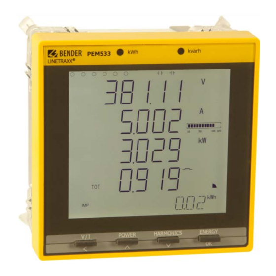
6. Operation 6.1 Getting to know the operating elements PEM533 kvarh POWER HARMONICS ENERGY Fig. 6.1: Operating elements Legend to operating elements Element Description LED kWh Pulse output, chapter " 6.5 LED indication" LED kvarh LC display Display mean values and total values (current, voltage) "V/I"... -
Page 26: Lcd Testing
Operation 6.2 LCD testing Pressing both the "POWER" and "HARMONICS" buttons simultaneously for > 2 seconds enters the LCD testing mode. During testing, all LCD segments are illuminated for one second and then turned off for 1 second. This cycle will be repeated 3 times. After completion of the test run, the device automatically returns to its normal display mode. -
Page 27: Getting To Know Standard Display Areas
Operation 6.3 Getting to know standard display areas The display can generally be divided into five areas. Fig. 6.3: Display areas Legend to the display areas Displays the indicators for digital input and output status (DI status, DO status) Measured values Harmonic Distortion HD, unbalance (unb), quadrant, measurement units Displays energy information such as active energy (import, export, net energy and total... - Page 28 Operation Description of standard display indications (ranges 1, 3 and 4) Area Segments Symbol description DI open DI closed DO open DO closed V, kV, A, %, Hz kW, MW, kvar, kVA, MVA Measurement units for U, I, THD, f Measurement units for P, Q, S Current value expressed as a per- inductive, capacitive...
-
Page 29: Power And Current Demand (Demand Display)
Operation 6.4 Power and current demand (Demand display) The demands are indicated on the display according to the following scheme: Fig. 6.5: Display: peak demand Description Peak demand value Peak demand timestamp (date): JJJJ.MM.TT Peak demand timestamp (time): HH:MM:SS Demand displays: Active power demand P Reactive power demand Q Apparent power demand... -
Page 30: Led Indication
Operation 6.5 LED indication The universal measuring device features two red LEDs on its front panel: kWh and kvarh. The two LED indicators are used for the indication of kWh and kvar, if the EN PULSE func- tion is enabled. The setting can be carried out in the setup menu using the buttons on the front or via the communications interface (only). -
Page 31: V/I" Button
Operation 6.7.1 "V/I" button Right Left column First line Second line Third line Fourth line column λ Ø U Ø I Power factor Ø U Ø U L1L2 L2L3 L3L1 Ø I Unbalance U Unbalance I Phase angle Phase angle Phase angle Phase angle I Phase angle I... - Page 32 Operation Right Left column First line Second line Third line Fourth line column Peak demand JJJJ.MM.TT hh:mm:ss this month Peak demand JJJJ.MM.TT hh:mm:ss last month Peak demand JJJJ.MM.TT hh:mm:ss last month Peak demand JJJJ.MM.TT hh:mm:ss last month Tab. 6.1: Display possibilities via the "V/I" button PEM533_D00013_01_M_XXEN/01.2016...
-
Page 33: Power" Button
Operation 6.7.2 "POWER" button Left Right First line Second line Third line Fourth line column column λ λ λ λ *dPF1 Displacement Displacement Displacement dPF2 dPF3 factor cos (φ) factor cos (φ) factor cos (φ) dTOT λ λ Demand P Demand Q Demand S Demand... - Page 34 Operation Left Right First line Second line Third line Fourth line column column Peak demand Q JJJJ.MM.TT hh:mm:ss last month Peak demand S JJJJ.MM.TT hh:mm:ss last month Tab. 6.2: Display possibilities via the "POWER" button Note: In "DELTA" mode, the display is skipped. PEM533_D00013_01_M_XXEN/01.2016...
-
Page 35: Harmonics" Button
Operation 6.7.3 "HARMONICS" button Left Right First line Second line Third line Fourth line column column THD U Ø THD Ø THD k-factor I k-factor I k-factor I TEHD TEHD TEHD Ø TEHD Even TEHD TEHD TEHD Ø TEHD Even TOHD TOHD TOHD... -
Page 36: Energy" Button
Operation Left Right First line Second line Third line Fourth line column column … HD31 harmonic harmonic harmonic Ø 31 harmonic HD31 harmonic I harmonic I harmonic I Ø 31 harmonic I Tab. 6.3: Display possibilities via the "HARMONICS" button 6.7.4 "ENERGY"... -
Page 37: Setup Using The Button At The Device
Operation 6.8 Setup using the button at the device Press the "ENERGY" button (> 3 s) to access the Setup mode. Press the "ENERGY" button again (> 3 s) to return to the display mode. To change parameters you must first enter the password. (factory setting: 0) 6.8.1 Setup: Function of the buttons... - Page 38 Operation Serial number Date update UPDAT Protocol version PROVER Software version SW-VER Info INFO Duration of display lighting BLTO SET Clear event memory CLR SOE Set time Clear pulse counter CLR DIC Clear peak demand CLR PDMD Set date Clear max/min values CLR MXMN Clear memory CLR SET...
-
Page 39: Setup: Possibilities
Operation 6.9 Setup: possibilities The table shows the messages indicated on the display, their meaning and the setting possibilities. Display entry Factory Level 1 Parameters Description Setting options setting Level 2 PROGRAM- Setup mode MING PASWORD Password Enter password PAS SET Change password? YES/NO NEW PAS New password... - Page 40 Operation Display entry Factory Level 1 Parameters Description Setting options setting Level 2 Set the measure- PERIOD Length of measu- ment period for 1, 2, 3, 5, 10, 15, rement period demand measure- 30, 60 (minutes) ment Number of mea- Set the number of surement periods sliding...
- Page 41 Operation Display entry Factory Level 1 Parameters Description Setting options setting Level 2 Clear values peak Clear peak CLR PDMD demand of this YES/NO demand month CLR DIC Clear pulse coun- YES/NO Clear event CLR SOE Clear event memory YES/NO memory Date Set current date...
- Page 42 Operation Comments on table 6.5: * Power factor λ rules Reactive power import Reactive power import Quadrant 2 Quadrant 1 Quadrant 2 Quadrant 1 Power factor (-) Power factor (+) Power factor (+) Power factor (-) Active power export (-) Active power import (+) Active power export (-) Active power export (+)
-
Page 43: Configuration Example: Setting Measuring Current Transformer
Operation 6.10 Configuration example: Setting measuring current transformer Ratio 1000 : 5 (= 200) Indication Button Description display ENERGY > 3 s PROGRAMMING PASWORD **** PASWORD 0 0 flashes (or password) PASWORD 0 0 Factory setting PAS SET NO SYS SET NO SYS SET NO NO flashes SYS SET YES... - Page 44 Operation PEM533_D00013_01_M_XXEN/01.2016...
-
Page 45: Application/Inputs And Outputs
7. Application/inputs and outputs 7.1 Digital inputs The device features six digital inputs which are internally operated with DC 24 V. Digital inputs are typically used for monitoring external states. The switching states of the digital inputs can be read from the LC display or from connected system compo- nents. -
Page 46: Energy
Application/inputs and outputs 7.4.2 Energy Basic energy parameters include Active energy (import, export, net energy and total energy in kWh) Reactive energy (import, export, net energy and total energy in kvarh) Apparent energy (S in kVAh) ... -
Page 47: Setpoints
Application/inputs and outputs 7.5 Setpoints The device supports two different types of setpoints: 1. Control setpoints for the general control applications and alarming. 2. Setpoints of the digital inputs and outputs: Provides control output actions in response to changes in digital input status. 7.5.1 Control setpoints The device features 9 user programmable control setpoints which provide extensive... -
Page 48: Setpoints Of The Digital Inputs And Outputs (Di Setpoint)
Application/inputs and outputs 3. Setpoint limit (active limit): Specifies the upper limits (over setpoint) resp. lower limits (under setpoint) that have to be violated before the setpoint becomes active (response threshold value). 4. Setpoint limit (inactive limit): Specifies the lower limits (under setpoint) resp. upper limits (over setpoint) that have to be violated before the setpoint becomes inactive, e.g. -
Page 49: Logging
Application/inputs and outputs 7.6 Logging 7.6.1 Peak demand log The PEM533 stores the peak demand of the last month and this month with timestamp for I and S . All values can be accessed through the front panel buttons as well as the communications interface. 7.6.2 Max/Min log The PEM533 stores each new maximum and minimum value of this month and last... - Page 50 Application/inputs and outputs This month Last month Maximum values Minimum values Maximum values Minimum values L2 max L2 min L2 max L2 min L3 max L3 min L3 max L3 min ges max ges min ges max ges min L1 max L1 min L1 max L1 min...
-
Page 51: Event Log (Soe Log)
Application/inputs and outputs 7.6.3 Event log (SOE log) The device can store up to 64 events. If there are more than 64 events, the newest event will replace the oldest event on a first-in-first-out basis: The 65 event will replace the first entry, the 66 the second one etc. -
Page 52: Unbalance
Application/inputs and outputs The following parameters are provided: TEHD TEHD TEHD TOHD TOHD TOHD Harmonics voltage harmonic harmonic harmonic … … … harmonic harmonic harmonic TEHD TEHD TEHD TOHD TOHD TOHD Harmonics k-factor k-factor k-factor current harmonic harmonic harmonic … …... -
Page 53: Modbus Register Map
This chapter provides a complete description of the Modbus register (protocol version 6.0) for the PEM533 series to facilitate access to information. In general, the registers are implemented as Modbus Read Only Registers (RO = read only) with the exception of the DO control registers, which are implemented as Write Only Registers (WO = write only). -
Page 54: Basic Measurements
Modbus Register Map 8.1 Basic measurements Register Property Description Format Scale/unit 0000 UINT32 ×100, V 0002 UINT32 ×100, V 0004 UINT32 ×100, V Ø U 0006 UINT32 ×100, V 0008 UINT32 ×100, V L1L2 0010 UINT32 ×100, V L2L3 0012 UINT32 ×100, V L3L1... - Page 55 Modbus Register Map Register Property Description Format Scale/unit 0046 INT32 ×1000, kVA λ 0048 INT16 ×1000, - λ 0049 INT16 ×1000, - λ 0050 INT16 ×1000, - λ 0051 INT16 ×1000, - 0052 UINT16 ×100, Hz 0053 UINT32 x1000, A 0055…0064 Reserved 0065...
- Page 56 Modbus Register Map Notes table 8.1: Only in the case of wye connection. "x 100, V" means that the voltage value returned in the register is 100 times the actual mea- sured value (therefore, the value of the register must be divided by 100 to obtain the measu- ring value).
-
Page 57: Energy Measurement
Modbus Register Map 8.2 Energy measurement Register Property Description Format Unit 0200 Active energy import UINT32 0202 Active energy export UINT32 0204 Active energy net amount INT32 0206 Total active energy UINT32 0208 Reactive energy import UINT32 kvarh 0210 Reactive energy export UINT32 kvarh 0212... - Page 58 Modbus Register Map Register Property Description Format Unit TOHD 0413 UINT16 x10,000 TOHD 0414 UINT16 x10,000 TOHD 0415 UINT16 x10,000 TOHD 0416 UINT16 x10,000 TOHD 0417 UINT16 x10,000 0418 UINT16 x10,000 0419 UINT16 x10,000 0420 UINT16 x10,000 0421 UINT16 x10,000 0422 UINT16 x10,000...
-
Page 59: Demand
Modbus Register Map 8.4 Demand Register Property Description Format Unit Demand U 1000 INT32 x100, V Demand U 1002 INT32 x100, V Demand U 1004 INT32 x100, V Ø Demand U 1006 INT32 x100, V Demand U 1008 INT32 x100, V L1L2 Demand U 1010... - Page 60 Modbus Register Map Register Property Description Format Unit λ 1048 Demand INT32 x1000 λ Demand 1050 INT32 x1000 λ 1052 Demand INT32 x1000 λ Demand 1054 INT32 x1000 1056 Demand f INT32 x100, Hz 1058 Demand voltage unbalance INT32 x1000 1060 Demand current unbalance INT32...
-
Page 61: Extreme Values Per Demand Measurement Time Frame
Modbus Register Map 8.5 Extreme values per demand measurement time frame 8.5.1 Maximum values demand Register Property Description Format Unit 1400 INT32 x100, V L1 max 1402 INT32 x100, V L2 max 1404 INT32 x100, V L3 max Ø U 1406 INT32 x100, V... - Page 62 Modbus Register Map Register Property Description Format Unit 1446 INT32 x1000, kVA ges max λ 1448 INT32 x1000 1 max λ 1450 INT32 x1000 2 max λ 1452 INT32 x1000 3 max λ 1454 INT32 x1000 ges max 1456 INT32 x100, Hz 1458 max.
-
Page 63: Minimum Values Demand
Modbus Register Map 8.5.2 Minimum values demand Register Property Description Format Unit 1600 INT32 x100, V L1 min 1602 INT32 x100, V L2 min 1604 INT32 x100, V L3 min Ø U 1606 INT32 x100, V LN min 1608 INT32 x100, V L1L2 min 1610... - Page 64 Modbus Register Map Register Property Description Format Unit λ 1648 INT32 x1000 1 min λ 1650 INT32 x1000 2 min λ 1652 INT32 x1000 3 min λ 1654 INT32 x1000 ges min 1656 INT32 x100, Hz 1658 min. voltage unbalance INT32 x1000 1660...
-
Page 65: Peak Demand
Modbus Register Map 8.6 Peak demand The value of the peak demand register is the actual value x 1,000, that means, to obtain a value in kW, kVA or kvar, the value of the register has to be divided by 1000. 8.6.1 Peak demand this month Register... - Page 66 Modbus Register Map Peak demand data structure Offset Property Description Format Note Peak demand value INT32 HiWord: Year 1…99 (year-2000) UINT16 LoWord: Month 1…12 HiWord: Date: Day 1…28/29/30/31 UINT16 LoWord: Hour 0…23 HiWord: Minute 0…59 UINT16 LoWord: Second 0…59 Tab. 8.9: Peak demand data structure PEM533_D00013_01_M_XXEN/01.2016...
-
Page 67: Max/Min Log
Modbus Register Map 8.7 Max/Min log 8.7.1 Max log of this month Register Eigenschaft Beschreibung Format Einheit 2000…2004 x100, V L1 max 2005…2009 x100, V L2 max 2010…2014 x100, V L3 max Ø U 2015…2019 x100, V LN max 2020…2024 x100, V L1L2 max 2025…2029... - Page 68 Modbus Register Map Register Eigenschaft Beschreibung Format Einheit 2110…2114 x1000, kVA L3 max 2115…2119 x1000, kVA ges max λ 2120…2124 x1000 1 max λ 2125…2129 x1000 2 max λ 2130…2134 x1000 3 max λ 2135…2139 x1000 ges max 2140…2144 x100, Hz 2145…2149 min.
-
Page 69: Min Log Of This Month
Modbus Register Map 8.7.2 Min log of this month Register Property Description Format 2300…2304 x100, V L1 min 2305…2309 x100, V L2 min 2310…2314 x100, V L3 min Ø U 2315…2319 x100, V LN min 2320…2324 x100, V L1L2 min 2325…2329 x100, V L2L3 min... - Page 70 Modbus Register Map Register Property Description Format 2410…2414 x1000, kVA L3 min 2415…2419 x1000, kVA ges min λ 2420…2424 x1000 1 min λ 2425…2429 x1000 2 min λ 2430…2434 x1000 3 min λ 2435…2439 x1000 ges min 2440…2444 x100, Hz see table 8.14 2445…2449 min.
-
Page 71: Max Log Of Last Month
Modbus Register Map 8.7.3 Max log of last month Register Property Description Format 2600…2604 x100, V L1 max 2605…2609 x100, V L2 max 2610…2614 x100, V L3 max Ø U 2615…2619 x100, V LN max 2620…2624 x100, V L1L2 max 2625…2629 x100, V L2L3 max... - Page 72 Modbus Register Map Register Property Description Format λ 2720…2724 x1000 1 max λ 2725…2729 x1000 2 max λ 2730…2734 x1000 3 max λ 2735…2739 x1000 ges max 2740…2744 x100, Hz 2745…2749 max. voltage unbalance x1000 see table 8.14 2750…2754 max. current unbalance x1000 2755…2759 x10,000...
-
Page 73: Min Log Of Last Month
Modbus Register Map 8.7.4 Min log of last month Register Property Description Format 2900…2904 x100, V L1 min 2905…2909 x100, V L2 min 2910…2914 x100, V L3 min Ø U 2915…2919 x100, V LN min 2920…2924 x100, V L1L2 min 2925…2929 x100, V L2L3 min... - Page 74 Modbus Register Map Register Property Description Format 3015…3019 x1000, kVA ges min λ 3020…3024 x1000 1 min λ 3025…3029 x1000 2 min λ 3030…3034 x1000 3 min λ 3035…3039 x1000 ges min 3040…3044 x100, Hz 3045…3049 min. voltage unbalance x1000 see table 8.14 3050…3054 min.
-
Page 75: Setup Parameters
Modbus Register Map 8.8 Setup parameters * = factory settings Register Property Description Format Range/unit 6000 Voltage transformer ratio UINT16 1*…2200 1*…6000 Measuring current transformer (current input 5 A) 6001 UINT16 ratio 1*…30000 (current input 1 A) 0 = WYE 6002 Wiring mode UINT16... - Page 76 Modbus Register Map Register Property Description Format Range/unit 6046 Setpoints DI1/ DI2 see "Digital input setpoint data struc- 6047 Setpoints DI3 / DI4 ture" on page 77. 6048 Setpoints DI5 / DI6 6049…6071 Reserved 6072…6080 Setpoint 1 6081…6089 Setpoint 2 6090…6098 Setpoint 3 6099…6107...
-
Page 77: Digital Input Setpoint Data Structure
Modbus Register Map 8.8.1 Digital input setpoint data structure Registers 6046, 6047 and 6048 Digital inputs DI1 and DI2 15…10 7…2 Triggers digital output Reserved Reserved Tab. 8.16: Register 6046 Digital inputs DI3 and DI4 15…10 7…2 Triggers digital output Reserved Reserved Tab. -
Page 78: Control Setpoints Data Structure
Modbus Register Map 8.8.2 Control setpoints data structure Offset Property Description Format Range/options 0 = disabled Type UINT16 1 = over setpoint 2 = under setpoint UINT16 1…16 Parameters Threshold value exceeded INT32 Value below release threshold INT32 Response threshold value delay UINT16 0…9999 (s) Release threshold value delay... -
Page 79: Event Log (Soe Log)
Modbus Register Map Trigger 3…21 Action Reserved Tab. 8.21: Setpoint trigger 8.9 Event log (SOE log) Each SOE event occupies 8 registers, as shown in the following table. The internal data structure of the event log is listed in table 8.23. Register Property Description... - Page 80 Modbus Register Map Offset Property Description Reserved Event classification (see table 8.24) HiWord: Year-2000 LoWord: Month (1…12) HiWord: Day (0…31) LoWord: Hour (1…23) HiWord: Minute (0…59) LoWord: Second (0…59) Millisecond (0…999) HiWord: Event value LoWord: Event value Tab. 8.23: Event data structure Event classification (SOE log) Event Event...
- Page 81 Modbus Register Map Event Event Event sub- value Description classification classification option Digital output 2 closed/open by setpoint 7…8 Reserved Digital output 1 closed/open by button on the front Digital output 2 closed/open by button on the front 11…14 Reserved Digital output 1 closed/open by DI setpoint Digital output 2 closed/open by DI setpoint 17…18...
- Page 82 Modbus Register Map Event Event Event sub- value Description classification classification option >-Setpoint U return Return value x 100 >-Setpoint U return Return value x 100 Return value x 1000 >-Setpoint I return >-Setpoint P return Return value >-Setpoint Q return Return value λ...
- Page 83 Modbus Register Map Event Event Event sub- value Description classification classification option Trigger value x 10.000 Under <-Setpoint THD Trigger value x 10.000 Under <-Setpoint TEHD Trigger value x 10.000 Under <-Setpoint TEHD Trigger value x 10.000 Under <-Setpoint TOHD Under <-Setpoint TOHD Trigger value x 1000 Under <-Setpoint demand P...
- Page 84 Modbus Register Map Event Event Event sub- value Description classification classification option Return value x 100 <-Setpoint demand I return Shows which DO is being triggered by DI set- point Bit 31 0 = open 1 = closed Shows which DI is being triggered by DO 1 = DI1 2 = DI2 Bits 16…30...
-
Page 85: Time Setting
Modbus Register Map Event Event Event sub- value Description classification classification option Max/Min log of this month cleared via com- munications Reserved 1…6 Reserved 1…17 Reserved Tab. 8.24: Event classification 8.10 Time setting There are two time register formats supported by PEM533: 1. -
Page 86: Dox Control
Modbus Register Map 8.11 DOx control The control register of the digital outputs are implemented as Write-Only registers (WO) and can be controlled with the function code 0x05. In order to query the current DO status, the register 0081 have to be read out. PEM533 supports the execution of commands to the outputs in two steps (ARM before EXECUTING): Before sending an open or close command to one of the outputs, it must be activated first. -
Page 87: Universal Measuring Device Information
Modbus Register Map 8.12 Universal measuring device information Register Property Description Format Note 9800… 9819 UINT16 see table 8.28 Model 9820 Software version UINT16 e.g.: 10000 = V1.00.00 9821 Protocol version UINT16 e.g.: 40 = V4.0 Software update date 9822 UINT16 (year-2000) e.g.: 080709 = July 9, 2008... - Page 88 Modbus Register Map PEM533_D00013_01_M_XXEN/01.2016...
-
Page 89: Technical Data
9. Technical data Insulation co-ordination Measuring circuit Rated insulation voltage..............................300 V Overvoltage category................................. III Pollution degree..................................2 Supply circuit Rated insulation voltage..............................300 V Overvoltage category.................................. II Pollution degree..................................2 Supply voltage Rated supply voltage ............................95…250 V Frequency range of ............................. DC, 44…440 Hz Power consumption ................................. - Page 90 Technical data PEM533-251 and PEM533-451 ..................................1 A CT transformer ratio........................... 1…30.000 Accuracy class according with 1 A measuring current transformer .............. 0.5 Accuracies (of measured value/of full scale value) Phase voltage ....................± 0.2 % of measured value L1-N L2-N L3-N Current ....................±0.2 % of measured value / +0.05% of full scale value...
-
Page 91: Standards And Certifications
Technical data Connection Connection ................................screw terminals Other Degree of protection, installation ............................IP20 Degree of protection, front ..............................IP52 Weight ..................................≤ 1100 g 9.1 Standards and certifications PEM533 was designed in accordance with the following standards: DIN EN 62053-22 (VDE 0418 Part 3-22) Electricity meter equipment (AC) - Particular requirements - Part 22: Static meters for active energy (classes 0,2 S and 0,5 S (IEC 62053);... - Page 92 Technical data PEM533_D00013_01_M_XXEN/01.2016...
-
Page 93: Index
INDEX Apparent power, calculation 42 Energy pulsing Application example 15 - activate/deactivate 40 Area of application 13 - Display 45 - LED indication 30 Event - Classification 80 Back-up fuses 19 - Memory 51 Button - Modbus register 79 - Energy 36 - HARMONICS 35 - POWER 33 - V/I 31... - Page 94 INDEX LED indication 30 - Modbus 79 Start 38 - Meaning of the buttons 37 - Overview diagram menu 37 Measuring current transformers 19 - SETUP mode 37 Modbus Support 8 - Basic measurements 54 - Digital outputs 86 - Energy measurement 57 - Event log 79 Technical data 89 - Measuring device information 87...
- Page 96 Bender GmbH & Co. KG Postfach 1161 • 35301 Gruenberg • Germany Londorfer Str. 65 • 35305 Gruenberg • Germany Tel.: +49 6401 807-0 Fax: +49 6401 807-259 E-Mail: info@bender.de www.bender.de Photos: Bender...
Need help?
Do you have a question about the PEM533 Series and is the answer not in the manual?
Questions and answers