Sign In
Upload
Manuals
Brands
Bender Manuals
Measuring Instruments
LINETRAXX PEM333-251
Bender LINETRAXX PEM333-251 Manuals
Manuals and User Guides for Bender LINETRAXX PEM333-251. We have
1
Bender LINETRAXX PEM333-251 manual available for free PDF download: Manual
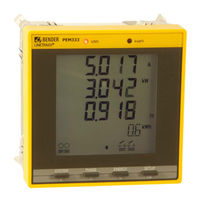
Bender LINETRAXX PEM333-251 Manual (108 pages)
Universal measuring device
Brand:
Bender
| Category:
Measuring Instruments
| Size: 4 MB
Table of Contents
Table of Contents
3
1 Making Effective Use of this Document
7
How to Use this Manual
7
Technical Support: Service and Support
8
Training Courses
9
Delivery Conditions, Guarantee, Warranty and Liability
10
2 Safety
11
Intended Use
11
Qualified Personnel
11
General Safety Instructions
12
3 Device Description
13
Area of Application
13
Device Features
13
Versions
15
Example of Application
16
Description of Function
17
Front View
18
Connecting Terminals
18
4 Installation and Connection
19
Project Planning
19
Safety Instructions
19
Installing the Device
20
Dimension Diagrams
20
Front Panel Mounting
21
Connection of the Device
21
Safety Information
21
Back-Up Fuses
22
Connection of Measuring Current Transformers
22
Instructions for Connection
22
Wiring Diagram
22
Pem330
23
Pem333
24
Pem333-P
26
Connection Diagram Voltage Inputs
28
Three-Phase 4-Wire System (TN, TT, IT Systems)
28
Three-Phase 3-Wire System
29
One-Phase 3-Wire System (1P3W)
30
One-Phase 2-Wire System (1P2W)
30
Connection Via Voltage Transformers
31
5 Commissioning
33
Check Proper Connection
33
Before Switching on
33
Switching on
33
System Integration and Visualisation
34
6 Operation
35
Getting to Know the Operating Elements
35
LC Display Test
36
Getting to Know Standard Display Indications
37
Power and Current Demand (Demand Display)
40
LED Indication
41
Standard Display
41
Data Display for Wye or Delta Connection
42
SYSTEM" Button
42
PHASE" Button
43
ENERGY" Button
45
Data Display for One-Phase Connections
45
Button „SYSTEM
45
Button „PHASE
47
Button „ENERGY
48
Setup Using the "SETUP" Button
49
SETUP": Meaning of the Buttons
49
SETUP: Overview Diagram Menu
50
Setup: Setting Possibilities
51
7 Application/Inputs and Outputs
59
Digital Inputs (PEM333
59
Digital Outputs (PEM333
59
Display Energy Pulsing
59
Digital Pulse Outputs (PEM333-P Only)
60
Power and Energy
60
Voltage and Current Phase Angles
60
Energy
60
Demand DMD
61
Setpoints (PEM333
61
Event Log (SOE Log)
63
Power Quality
63
Total Harmonic Distortion
63
Unbalance
64
8 Modbus Register Map
65
Basic Measuring Values
66
Energy Measurement
71
Energy Measurement Per Phase
72
Peak Demand
74
Total Harmonic Distortion (THD) and K-Factor
75
Connection Fault Detection
76
Setup Parameters
78
Event Log (SOE Log)
83
Max/Min Log
87
Maximum Values
87
Minimum Values
90
Data Structure Max/Min Log
93
Time Setting
94
Dox Control
95
Universal Measuring Device Information
96
9 Technical Data
99
Standards and Certifications
102
Ordering Information
102
Index
103
Advertisement
Advertisement
Related Products
Bender PEM330
Bender PEM333
Bender PEM353
Bender LINETRAXX PEM330-251
Bender LINETRAXX PEM333-255P
Bender LINETRAXX PEM333-251P
Bender LINETRAXX PEM575 Series
Bender LINETRAXX PEM575-251
Bender LINETRAXX PEM575-455
Bender PEM735
Bender Categories
Measuring Instruments
Monitor
Control Unit
Control Panel
Relays
More Bender Manuals
Login
Sign In
OR
Sign in with Facebook
Sign in with Google
Upload manual
Upload from disk
Upload from URL