Sign In
Upload
Manuals
Brands
Ulvac Manuals
Accessories
G-TRAN SW1-2
User Manuals: Ulvac G-TRAN SW1-2 Pirani Vacuum Gauge
Manuals and User Guides for Ulvac G-TRAN SW1-2 Pirani Vacuum Gauge. We have
1
Ulvac G-TRAN SW1-2 Pirani Vacuum Gauge manual available for free PDF download: Instruction Manual
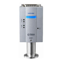
Ulvac G-TRAN SW1-2 Instruction Manual (49 pages)
Pirani Vacuum Gauge Sensor Unit
Brand:
Ulvac
| Category:
Accessories
| Size: 2 MB
Table of Contents
Prior to Operation
3
Safety Notations
3
Safety Precautions
4
Revision History
7
Table of Contents
8
1 Specifications
10
Standard Specifications
10
Unpacking and Quantity Check
11
Dimensional Drawings
12
SW1-1/SW1-2 Dimensional Drawings
12
SWP-16 Dimensional Drawings
13
Unpacking and Quantity Check
13
2 Cautions in Operation
14
Checks Immediately after Operation
14
Cautions on Operating Environment
14
Cautions in Operation
15
Installing the Instrument
15
Sensor Installing Environment
15
Installing the Sensor Head
16
3 Names of Components and Description of Functions
17
Controller Unit
17
Front Panel Standard Type SW1-1
18
Front Panel Serial Communication Type SW1-2
19
Input / Output Connector Standard Type SW1-1
20
Input/Output Connector Serial Communication Type SW1-2
21
4 Circuit in the Power Supply
22
5 Signals
23
Pressure Signal Output (SW1-1 and SW1-2)
23
Pressure Converting Equation
23
Output of Measurement Value in each State
23
I/O Signal Output (Standard Type SW1-1 Only)
24
Sensor Error Signal (Standard Type SW1-1 Only)
24
Setpoint Actuating Signal (Standard Type SW1-1 Only)
24
I/O Input Signal (Standard Type SW1-1 Only)
25
6 Setting the Setpoint (Standard Type SW1-1 Only)
26
Set Point ON/OFF Pressure
26
Wiring in Setting Setpoint
26
Setting of Setpoint
27
7 How to Use Serial Communication (Serial Communication Type SW1-2 Only)
28
Communication Specifications
28
Various Settings
28
Connection Diagram
28
Baud Rate Setting
29
Address Setting
29
Standard Data Format
30
List of Commands
30
When Receiving Is Normal
30
When Receipt Is Not Normal
30
Command
31
Reading the Measurement Value/Status
31
Zero Point Adjustment Command
31
Atmospheric Pressure Adjustment Command
31
Zero Point and Atmospheric Pressure Adjustment Clear Command
31
Status Reading
31
Reading Software Version
31
Reading Setpoint 1 Set Value
32
Reading the Setpoint 2 Set Value
32
Writing the Setpoint 1 Set Value
32
Writing the Setpoint 2 Set Value
32
Checksum
33
Status
34
SH (Higher Case of Status)
34
Lower Case of Status)
34
ASCII Code Table
35
8 Zero Point Adjustment and Atmospheric Pressure Adjustment
36
Checking the Completion of Adjustment
36
Adjusting Method
36
Zero Point, ATM Adjustment, Adjustment Resetting
37
Zero Point Adjustment
37
Atmospheric Pressure Adjustment
37
Resetting
37
Memory Function
37
9 Replacement of Sensor Head
38
Tool
38
Removing the Sensor Head
38
Installing the Sensor Head
39
Leak Test
39
Adjustment after Replacement of Sensor Head
39
10 Troubleshooting
40
Checking the Filament and Temperature Sensor for Burnout
43
Insulation between Sensor Head Pin and Case
43
11 Technical Data
44
Dependence on Gas Specie
44
Zero Point Adjustment and Atmospheric Pressure Adjustment
45
Scheduled Adjustment
45
12 Warranty
46
13 China Rohs Declaration
47
14 EC Declaration of Conformity
48
15 Certificate of Decontamination
49
Advertisement
Advertisement
Related Products
Ulvac G-Tran SH2-1
Ulvac G-Tran SH2-2
Ulvac G-TRAN SW1-1
Ulvac ST2-1
Ulvac ST2-2
Ulvac G-Tran SP1
Ulvac G-Tran SW1
Ulvac G-Tran SH2
Ulvac ST200-A
Ulvac ST-200-R
Ulvac Categories
Water Pump
Air Compressor
Power Supply
Measuring Instruments
Industrial Equipment
More Ulvac Manuals
Login
Sign In
OR
Sign in with Facebook
Sign in with Google
Upload manual
Upload from disk
Upload from URL