Table of Contents
Advertisement
Quick Links
MP45E
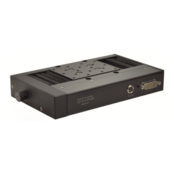
M-605 High-Precision Linear Stage
User Manual
Version: 1.2.0
PI miCos GmbH, Freiburger Strasse 30, 79427 Eschbach, Germany
Phone +49 7634 5057-0, Fax +49 7634 5057-99, Email info@pimicos.com, www.pi.ws
Date: 2019-07-02
This document describes the following products:
M-605.1DD:
Compact precision linear stage, 25 mm travel
range, 0.1 μm linear encoder, ActiveDrive DC
motor
M-605.2DD:
Compact precision linear stage, 50 mm travel
range, 0.1 μm linear encoder, ActiveDrive DC
motor
Advertisement
Table of Contents

Subscribe to Our Youtube Channel
Related Manuals for PI M-605 Series


Summary of Contents for PI M-605 Series
- Page 1 0.1 μm linear encoder, ActiveDrive DC motor M-605.2DD: Compact precision linear stage, 50 mm travel range, 0.1 μm linear encoder, ActiveDrive DC motor PI miCos GmbH, Freiburger Strasse 30, 79427 Eschbach, Germany Phone +49 7634 5057-0, Fax +49 7634 5057-99, Email info@pimicos.com, www.pi.ws...
- Page 2 The patents held by PI can be found in our list at http://www.physikinstrumente.com/en/about-pi/patents. © 2019 Physik Instrumente (PI) GmbH & Co. KG, Karlsruhe, Germany. The text, photographs, and drawings in this manual are protected by copyright. With regard thereto, Physik Instrumente (PI) GmbH & Co. KG reserves all rights.
-
Page 3: Table Of Contents
Contents About this Document Objective and Target Group of this User Manual ............1 Symbols and Typographic Conventions..............1 Downloading Manuals ....................2 Safety Intended Use ......................3 General Safety Instructions ..................3 Organizational Measures .................... 3 Product Description Model Overview ......................5 Scope of Delivery ...................... - Page 4 Maintenance Troubleshooting Customer Service Technical Data 10.1 Specifications ......................21 10.1.1 Data Table ....................21 10.1.2 Maximum Ratings ..................22 10.1.3 Ambient Conditions and Classifications ............22 10.1.4 Limit Switch Specifications ................23 10.2 Dimensions ....................... 24 10.2.1 M-605.1DD ....................24 10.2.2 M-605.2DD ....................
-
Page 5: About This Document
1 About this Document About this Document Objective and Target Group of this User Manual This manual is designed to help the reader to install and operate the M-605 Linear Positioning Stages. It assumes that the reader has a fundamental understanding of basic servo systems, as well as motion control concepts and applicable safety procedures. -
Page 6: Downloading Manuals
1 About this Document Downloading Manuals The devices and software tools from PI that are mentioned in this documentation are described in separate manuals. The manuals are available for download on our website. INFORMATION If a manual is missing or problems occur with downloading: ... -
Page 7: Safety
2 Safety Safety Intended Use The M-605 is a laboratory device as defined by DIN EN 61010. It is intended for indoor use and use in an environment which is free of dirt, oil, and lubricants. In accordance with its design, the M-605 is intended for single-axis positioning, adjusting and shifting of loads at different velocities. -
Page 9: Product Description
3 Product Description Product Description Model Overview Product number Description M-605.1DD Compact precision linear stage, 25 mm travel range, 0.1 µm linear encoder, ActiveDrive DC motor M-605.2DD Compact precision linear stage, 50 mm travel range, 0.1 µm linear encoder, ActiveDrive DC motor Scope of Delivery Product number Description... -
Page 10: Technical Features
If the platform is on the “positive side” the reference signal is +5 V, while if the platform is on the “negative side,” the signal level is 0 V. Most PI motor controllers and Windows libraries offer the option of starting a search run for the reference point using the current reference sensor signal to determine the appropriate direction. -
Page 11: Unpacking
2. Compare the contents with the items listed in the contract and the packing list. 3. Inspect the contents for signs of damage. If there is any sign of damage or missing parts, contact PI immediately. 4. Keep all packaging materials in case the product needs to be returned. -
Page 13: Installation
5 Installation Installation General Notes on Installation CAUTION Risk of crushing by moving parts! Risk of minor injuries from crushing between the moving parts of the M-605 or the load and a fixed part or obstacle. Use safeguards to protect limbs in areas where they could be caught by moving parts. ... -
Page 14: Affixing The Load To The M-605
5 Installation − Hex wrench Mounting the positioner onto a surface 1. Place the positioner on the surface so that the corresponding mounting holes in the positioner and the surface are in line. 2. Tighten all screws in the mounting holes selected. 3. -
Page 15: Connecting The Power Supply To The M-605
5 Installation Suitable tool for tightening the screws of the connector Connecting the M-605 to a controller 1. If necessary: Remove the protective caps from all connections of the M-605. 2. Connect the M-605 and the controller to each other by means of the motor cable. 3. -
Page 17: Startup
6 Startup Startup General Notes on Startup CAUTION Risk of crushing by moving parts! Risk of minor injuries from crushing between the moving parts of the M-605 or the load and a fixed part or obstacle. Never put your finger anywhere where the moving platform or any connected object could possibly trap it. -
Page 18: Starting And Operating The M-605
1. Start the controller (see user manual for the controller). 2. Configure the controller for the M-605 during startup: − If you are using a digital controller from PI: In the PC software, select the entry in the positioner database that matches the used M-605 model exactly. −... - Page 19 7 Maintenance Maintenance When operated in a clean environment, no maintenance is required. If the stages are operated in extremely dusty environments, we recommend cleaning and greasing the ballscrew and linear bearings from time to time. The time interval depends on the degree of contamination and can vary from 100 to 800 operating hours.
- Page 21 8 Troubleshooting Troubleshooting Fault: The positioner does not move, no operating noise can be heard Possible causes Remedial measures Reset the motion error (see user manual of the controller). There is a motion error. Check the connecting cable (p. 10). Controller not connected correctly ...
- Page 23 9 Customer Service Customer Service For inquiries and orders, contact your PI sales engineer or send us an email (service@pi.de). If you have any questions concerning your system, provide the following information: Product and serial numbers of all products in the system ...
-
Page 25: Technical Data
10 Technical Data Technical Data 10.1 Specifications 10.1.1 Data Table M-605.1DD M-605.2DD Unit Active axes Motion and positioning M-605.1DD M-605.2DD Unit Travel range Integrated sensor Linear encoder Linear encoder Sensor resolution µm Design resolution µm Minimum incremental motion µm Unidirectional repeatability µm Bidirectional repeatability µm... -
Page 26: Maximum Ratings
10 Technical Data Drive properties M-605.1DD M-605.2DD Unit Motor type DC motor, ActiveDrive DC motor, ActiveDrive Operating voltage 24 (PWM) 24 (PWM) Motor power Reference and limit switches Hall effect Hall effect Miscellaneous M-605.1DD M-605.2DD Unit Operating temperature range -20 to 65 -20 to 65 °C Material... -
Page 27: Limit Switch Specifications
10 Technical Data 10.1.4 Limit Switch Specifications Type Magnetic (Hall-effect) sensors, can be used with bipolar CMOS circuits Supply voltage +5...+24 V / GND, supplied by the motor controller through the motor connector Signal output TTL level Sink / source current ±... -
Page 28: Dimensions
10 Technical Data 10.2 Dimensions Dimensions in mm. Note that the decimal places are separated by a comma in the drawings. 10.2.1 M-605.1DD Version: 1.2.0 MP45E M-605 High-Precision Linear Stage... -
Page 29: M-605.2Dd
10 Technical Data 10.2.2 M-605.2DD M-605 High-Precision Linear Stage MP45E Version: 1.2.0... -
Page 30: M-605.Av1
10 Technical Data 10.2.3 M-605.AV1 Version: 1.2.0 MP45E M-605 High-Precision Linear Stage... -
Page 31: Pin Assignment
10 Technical Data 10.3 Pin Assignment 10.3.1 Controller Connector D-Sub 15 (m) connector Signal Direction Control for optional motor brake (0 to 24 V) Input Not connected PWM MAGN Input +5 V Input PLIMIT (positive limit switch) Output GND (Limit) Encoder A(-) Output Encoder B(-) -
Page 33: Old Equipment Disposal
Dispose of your old equipment according to international, national, and local rules and regulations. In order to fulfil the responsibility as the product manufacturer, PI miCos GmbH undertakes environmentally correct disposal of all old PI miCos equipment made available on the market after 13 August, 2005 without charge. - Page 35 12 EU Declaration of Conformity EU Declaration of Conformity An EU Declaration of Conformity has been issued for the M-605 in accordance with the following European directives: • EMC Directive • Low Voltage Directive • Safety of Machinery The standards applied for certifying the conformity are listed below. •...
Need help?
Do you have a question about the M-605 Series and is the answer not in the manual?
Questions and answers