Table of Contents
Advertisement
Advertisement
Table of Contents

Related Manuals for Siemens SINAMICS S120M


Summary of Contents for Siemens SINAMICS S120M
- Page 3 ___________________ SINAMICS S120M Distributed Drive Foreword Technology Fundamental safety instructions ___________________ SINAMICS System overview ___________________ Adapter Module 600 S120 SINAMICS S120M ___________________ Distributed Drive Technology S120M DRIVE-CLiQ Extension Manual ___________________ Hybrid Cabinet Bushing ___________________ Cabinet design and EMC S120M ___________________...
- Page 4 Note the following: WARNING Siemens products may only be used for the applications described in the catalog and in the relevant technical documentation. If products and components from other manufacturers are used, these must be recommended or approved by Siemens. Proper transport, storage, installation, assembly, commissioning, operation and maintenance are required to ensure that the products operate safely and without any problems.
-
Page 5: Foreword
(mailto:docu.motioncontrol@siemens.com). My Documentation Manager At the following address (http://www.siemens.com/mdm), you can find information on how to create your own individual documentation based on Siemens' content, and adapt it for your own machine documentation. Training At the following address (http://www.siemens.com/sitrain), you can find information about SITRAIN (Siemens training on products, systems and solutions for automation and drives). - Page 6 • Units SINAMICS S120 Equipment Manual for Chassis Power Units • SINAMICS S120 Equipment Manual for AC Drives • SINAMICS S120M Manual Distributed Drive Technology • SINAMICS S120 Manual Booksize C/D series • SINAMICS HLA System Manual Hydraulic Drive •...
- Page 7 You can find the EC Declaration of Conformity for the relevant directives as well as the relevant certificates, prototype test certificates, manufacturers declarations and test certificates for functions relating to functional safety ("Safety Integrated") in the Internet at the following address (http://support.automation.siemens.com/WW/view/en/21901735/134200). SINAMICS S120M Distributed Drive Technology Manual, (GH12), 12/2014, 6SL3097-4AW00-0BP3...
- Page 8 Foreword You can obtain an up-to-date list of currently certified components on request from your local Siemens office. If you have any questions relating to certifications that have not yet been completed, please ask your Siemens contact person. Note You can find certificates for the North American market on the Internet page of the certifier: •...
- Page 9 Spare parts are available on the Internet at the following address (http://support.automation.siemens.com/WW/view/en/16612315). Ground symbols Table 2 Symbols Symbol Meaning Connection for protective conductor (PE) Ground (e.g. M 24 V) Connection for function potential bonding SINAMICS S120M Distributed Drive Technology Manual, (GH12), 12/2014, 6SL3097-4AW00-0BP3...
- Page 10 Foreword SINAMICS S120M Distributed Drive Technology Manual, (GH12), 12/2014, 6SL3097-4AW00-0BP3...
-
Page 11: Table Of Contents
Field of application ......................23 Platform Concept and Totally Integrated Automation ............24 Introduction ........................26 SINAMICS S120 components .................... 29 2.4.1 SINAMICS S120M component overview ................29 2.4.2 Component specification according to UL ................31 2.4.3 Overview of Line Modules ....................37 2.4.4... - Page 12 Characteristics .........................107 Hybrid Cabinet Bushing ......................109 Description ........................109 Safety instructions for the Hybrid Cabinet Bushing ............110 Interface description ......................111 Dimension drawing ......................112 Mounting ..........................113 Technical data ........................114 6.6.1 Characteristics .........................114 SINAMICS S120M Distributed Drive Technology Manual, (GH12), 12/2014, 6SL3097-4AW00-0BP3...
- Page 13 Forming the DC link capacitors ..................154 8.3.1 Central components (AM600) ..................154 8.3.2 Distributed components ....................156 Appendix ..........................157 List of abbreviations ......................157 Documentation overview ....................166 Index ............................167 SINAMICS S120M Distributed Drive Technology Manual, (GH12), 12/2014, 6SL3097-4AW00-0BP3...
- Page 14 Table of contents SINAMICS S120M Distributed Drive Technology Manual, (GH12), 12/2014, 6SL3097-4AW00-0BP3...
-
Page 15: Fundamental Safety Instructions
Touching live components can result in death or severe injury. • Only use power supplies that provide SELV (Safety Extra Low Voltage) or PELV- (Protective Extra Low Voltage) output voltages for all connections and terminals of the electronics modules. SINAMICS S120M Distributed Drive Technology Manual, (GH12), 12/2014, 6SL3097-4AW00-0BP3... - Page 16 • Install devices without a protective housing in a metal control cabinet (or protect the device by another equivalent measure) in such a way that contact with fire is prevented. • Ensure that smoke can only escape via controlled and monitored paths. SINAMICS S120M Distributed Drive Technology Manual, (GH12), 12/2014, 6SL3097-4AW00-0BP3...
- Page 17 • Check that the warning labels are complete based on the documentation. • Attach any missing warning labels to the components, in the national language if necessary. • Replace illegible warning labels. SINAMICS S120M Distributed Drive Technology Manual, (GH12), 12/2014, 6SL3097-4AW00-0BP3...
- Page 18 Note Important safety notices for Safety Integrated functions If you want to use Safety Integrated functions, you must observe the safety notices in the Safety Integrated manuals. SINAMICS S120M Distributed Drive Technology Manual, (GH12), 12/2014, 6SL3097-4AW00-0BP3...
-
Page 19: Safety Instructions For Electromagnetic Fields (Emf)
– Wearing ESD shoes or ESD grounding straps in ESD areas with conductive flooring • Only place electronic components, modules or devices on conductive surfaces (table with ESD surface, conductive ESD foam, ESD packaging, ESD transport container). SINAMICS S120M Distributed Drive Technology Manual, (GH12), 12/2014, 6SL3097-4AW00-0BP3... -
Page 20: Industrial Security
Siemens recommends strongly that you regularly check for product updates. For the secure operation of Siemens products and solutions, it is necessary to take suitable preventive action (e.g. cell protection concept) and integrate each component into a holistic, state-of-the-art industrial security concept. -
Page 21: Residual Risks Of Power Drive Systems
Inverters of the Open Type / IP20 degree of protection must be installed in a metal control cabinet (or protected by another equivalent measure) such that the contact with fire inside and outside the inverter is not possible. SINAMICS S120M Distributed Drive Technology Manual, (GH12), 12/2014, 6SL3097-4AW00-0BP3... - Page 22 Assuming that conductive contamination at the installation site can definitely be excluded, a lower degree of cabinet protection may be permitted. For more information about residual risks of the components in a drive system, see the relevant sections in the technical user documentation. SINAMICS S120M Distributed Drive Technology Manual, (GH12), 12/2014, 6SL3097-4AW00-0BP3...
-
Page 23: System Overview
System overview Field of application SINAMICS is the family of drives from Siemens designed for machine and plant engineering applications. SINAMICS offers solutions for all drive tasks: ● Simple pump and fan applications in the process industry. ● Complex single drives in centrifuges, presses, extruders, elevators, as well as conveyor and transport systems ●... -
Page 24: Platform Concept And Totally Integrated Automation
– the dynamic performance and accuracy – the integration of extensive technological functions in the drive control system ● SINAMICS S120M for distributed servo drive technology S120M is a synchronous motor with integrated power unit, which is connected to a central Control Unit via DRIVE-CLiQ. - Page 25 System overview 2.2 Platform Concept and Totally Integrated Automation Figure 2-2 SINAMICS as part of the Siemens modular automation system SINAMICS S120M Distributed Drive Technology Manual, (GH12), 12/2014, 6SL3097-4AW00-0BP3...
-
Page 26: Introduction
System overview 2.3 Introduction Introduction System overview Figure 2-3 System overview, SINAMICS S120 with distributed servo drive technology S120M SINAMICS S120M Distributed Drive Technology Manual, (GH12), 12/2014, 6SL3097-4AW00-0BP3... - Page 27 Users can choose from many different harmonized components and functions to create a solution that best meets their requirements. "SIZER for SIEMENS Drives", a powerful engineering tool, makes it easier to choose and determine the optimum drive configuration.
- Page 28 Since this data can be called up electronically on site or remotely, all the components used in a machine can always be individually identified, which helps simplify servicing. SINAMICS S120M Distributed Drive Technology Manual, (GH12), 12/2014, 6SL3097-4AW00-0BP3...
-
Page 29: Sinamics S120 Components
System overview 2.4 SINAMICS S120 components SINAMICS S120 components 2.4.1 SINAMICS S120M component overview Figure 2-4 Overview of SINAMICS S120 with SINAMICS S120M distributed drive technology SINAMICS S120M Distributed Drive Technology Manual, (GH12), 12/2014, 6SL3097-4AW00-0BP3... - Page 30 The booksize compact format is thus particularly well suited for integration into machines with high dynamic requirements and confined installation conditions. The booksize compact format offers the following cooling options: ● Internal air cooling ● Cold plate cooling SINAMICS S120M Distributed Drive Technology Manual, (GH12), 12/2014, 6SL3097-4AW00-0BP3...
-
Page 31: Component Specification According To Ul
2.4.2 Component specification according to UL The components of the SINAMICS S120M drive system are UL-certified. The certification is indicated on the products using the UL Listing Mark. You can find proof of the certification on the Internet at http://www.ul.com under "Tools / Online Certifications Directory" by entering the file number or the "Name". - Page 32 (Feedthrough current X1/X2) Max. input current 0.56 0.52 0.52 0.54 0.54 48 V electronics power supply Signal interface X3 Output voltage Max. output current terminal 1 Max. output current terminal 2 (resistive) SINAMICS S120M Distributed Drive Technology Manual, (GH12), 12/2014, 6SL3097-4AW00-0BP3...
- Page 33 The S120M modules provide motor overload protection at a level of 125 % of the nominal motor current. For the brake release on connector X4 connect a power supply rated 24 Vdc, Class 2 only SINAMICS S120M Distributed Drive Technology Manual, (GH12), 12/2014, 6SL3097-4AW00-0BP3...
- Page 34 Voltage Current Core cross-section To connect the distributed components HCB, DQE and S120M with one another and to the AM 600, it is only permissible to use the 6FX8002-7HY..-..Hybrid Cable. SINAMICS S120M Distributed Drive Technology Manual, (GH12), 12/2014, 6SL3097-4AW00-0BP3...
- Page 35 7TE25-5Axy 7TE28-0Axy x stands for any letter and y for any number Operation of the components of the SINAMICS S120M system on Active Line Modules Booksize with 120 kW power is not certified. Table 2- 8 Basic Line Modules booksize...
- Page 36 Line fuses for the Line Modules must be installed in compliance with the requirements specified in the SINAMICS S120 Manual GH2 Booksize power units. Note The SINAMICS S120M Modular Drive System is intended for use only in industrial machinery NFPA 79 applications. SINAMICS S120M Distributed Drive Technology...
-
Page 37: Overview Of Line Modules
Smart Line Modules are equipped with DRIVE-CLiQ interfaces for communicating with the Control Unit. The 5 kW and 10 kW Smart Line Modules must be connected with the Control Unit via terminals. Figure 2-5 Overview of Line Modules SINAMICS S120M Distributed Drive Technology Manual, (GH12), 12/2014, 6SL3097-4AW00-0BP3... - Page 38 Characteristics of the Basic Line Modules ● Unregulated DC link voltage ● No regenerative feedback capability ● For all Basic Line Modules, an outgoing circuit for DC link busbar is possible on both sides. SINAMICS S120M Distributed Drive Technology Manual, (GH12), 12/2014, 6SL3097-4AW00-0BP3...
-
Page 39: Overview Of Motor Modules
Depending on the type (Single or Double), each Motor Module has one or two DRIVE-CLiQ interfaces for connecting the motor encoder evaluation (Sensor Modules). Figure 2-6 Overview of Motor Modules in booksize format SINAMICS S120M Distributed Drive Technology Manual, (GH12), 12/2014, 6SL3097-4AW00-0BP3... -
Page 40: Overview Of Distributed S120M Components
● Integration in system diagnostics 2.4.5 Overview of distributed S120M components SINAMICS S120M is the distributed version of the SINAMICS S120 booksize family. Hardware The SINAMICS S120M distributed system comprises the following units: ● S120M (1FK7 synchronous motor with integrated Power Module encoder) ●... - Page 41 ● As Control Unit or control, all multi-axis CUs in the SINAMICS/SIMOTION/SINUMERIK range can be used (CU320-2, D4xx-2, CX32-2, NCUxx). The releases of the S120M on the corresponding systems are published via the Siemens Industry Online Support Portal (http://support.automation.siemens.com). ● Firmware and parameterization are updated via DRIVE-CLiQ.
- Page 42 – X1 (IN): Hybrid connector – X2 (OUT): Hybrid connector – X200: DRIVE-CLiQ ● Hybrid Cabinet Bushing – X1 (IN): Hybrid connector – X2 (OUT): Hybrid connector – X201 (IN): DRIVE-CLiQ – X202 (OUT): DRIVE-CLiQ SINAMICS S120M Distributed Drive Technology Manual, (GH12), 12/2014, 6SL3097-4AW00-0BP3...
-
Page 43: System Data
System overview 2.5 System Data System Data Technical data The following technical data applies to components in the SINAMICS S120 booksize drive system and SINAMICS S120M distributed drive system. Table 2- 11 Electrical data Electrical data Line connection voltage 3-ph. 380 VAC ... 480 VAC ±10%(-15% < 1 min) - Page 44 3.5 K per 500 m. Above 2,000 m installation altitude, see characteristic for voltage derating Table 2- 13 Certificates Certificates Declarations of Conformity CE (Low-Voltage and EMC Directives) Approvals ULus SINAMICS S120M Distributed Drive Technology Manual, (GH12), 12/2014, 6SL3097-4AW00-0BP3...
-
Page 45: Derating As A Function Of The Installation Altitude
The products described in this manual are extensively recyclable on account of the low-toxic composition of the materials used. For environmentally-compliant recycling and disposal of your electronic waste, please contact a company for the disposal of electronic waste. SINAMICS S120M Distributed Drive Technology Manual, (GH12), 12/2014, 6SL3097-4AW00-0BP3... - Page 46 System overview 2.7 Recycling and disposal SINAMICS S120M Distributed Drive Technology Manual, (GH12), 12/2014, 6SL3097-4AW00-0BP3...
-
Page 47: Adapter Module 600
The 48 VDC cables are electronically protected against overload and short-circuit. ● Boosting the DRIVE-CLiQ signal using a repeater function (level and signal waveform) and feeding this into the Hybrid Cable. SINAMICS S120M Distributed Drive Technology Manual, (GH12), 12/2014, 6SL3097-4AW00-0BP3... - Page 48 The AM600 is not an active DRIVE-CLiQ node. The AM600 only feeds into one DRIVE-CLiQ line in the Hybrid Cable. See also 24 V power supply and connection of components (Page 117) X24 24 V terminal adapter (Page 120) SINAMICS S120M Distributed Drive Technology Manual, (GH12), 12/2014, 6SL3097-4AW00-0BP3...
-
Page 49: Safety Instructions For Adapter Modules
– It complies with the local regulations for equipment with increased leakage current. Cables laid within control cabinets or closed machine housings are considered to be adequately protected against mechanical damage. SINAMICS S120M Distributed Drive Technology Manual, (GH12), 12/2014, 6SL3097-4AW00-0BP3... - Page 50 There is also a risk of an electric shock. This can result in serious injury or death. • Only use adapters (DC link adapters and DC link rectifier adapters) released by Siemens for the connection to the DC link. WARNING Fire hazard due to overheating because of inadequate ventilation clearances Inadequate ventilation clearances can cause overheating with a risk for personnel through smoke development and fire.
-
Page 51: Interface Description
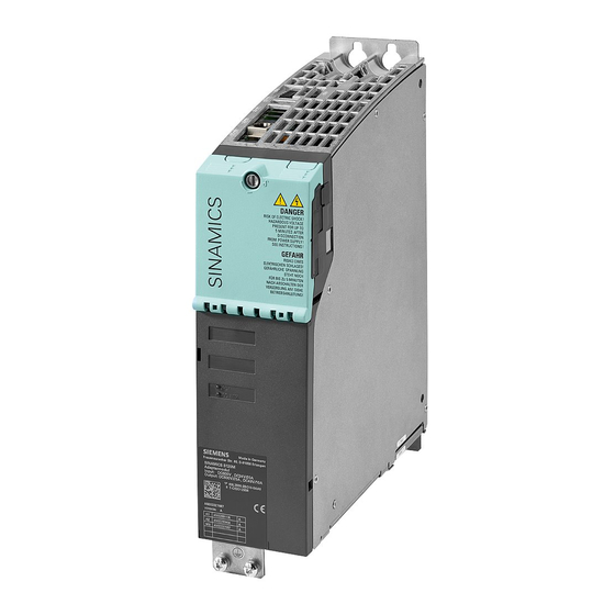
3.3 Interface description Note Mounting position in the control cabinet • Mount the Adapter Modules 600 vertically in the control cabinet. Interface description 3.3.1 Overview Figure 3-1 Adapter Module 600 (AM600) SINAMICS S120M Distributed Drive Technology Manual, (GH12), 12/2014, 6SL3097-4AW00-0BP3... -
Page 52: X1 Hybrid Connector
The terminal has 0 V, if the DC link voltage is > 50 V. Note: Hazardous DC link voltages may be present at any time regardless of the state of the system. SINAMICS S120M Distributed Drive Technology Manual, (GH12), 12/2014, 6SL3097-4AW00-0BP3... -
Page 53: X201 Drive-Cliq Interface
Transmit data - Receive data + Reserved, do not use Reserved, do not use Receive data - Reserved, do not use Reserved, do not use Reserved, do not use Reserved, do not use SINAMICS S120M Distributed Drive Technology Manual, (GH12), 12/2014, 6SL3097-4AW00-0BP3... -
Page 54: Connection Example
The current carrying capacity of the DO must be observed; an output interface may have to be used. Contact established via rear mounting panel or shielding buses in accordance with the EMC installation guideline Figure 3-2 Connection example, Adapter Module 600 (AM600) SINAMICS S120M Distributed Drive Technology Manual, (GH12), 12/2014, 6SL3097-4AW00-0BP3... - Page 55 Adapter Module 600 3.4 Connection example Figure 3-3 Connection example, AM600:X21 (operating states) at the Control Unit CU320-2 DP (schematic) SINAMICS S120M Distributed Drive Technology Manual, (GH12), 12/2014, 6SL3097-4AW00-0BP3...
-
Page 56: Meaning Of The Leds
Independent of the state of the LED "DC LINK", hazardous DC link voltages can be present. This means that when live components are touched this can result in death or serious injury. • Observe the warning information on the component. SINAMICS S120M Distributed Drive Technology Manual, (GH12), 12/2014, 6SL3097-4AW00-0BP3... -
Page 57: Dimension Drawing
Adapter Module 600 3.6 Dimension drawing Dimension drawing Figure 3-4 Dimension drawing, Adapter Module 600 (AM600), all data in mm or (inch) SINAMICS S120M Distributed Drive Technology Manual, (GH12), 12/2014, 6SL3097-4AW00-0BP3... -
Page 58: Mounting
Figure 3-5 Mounting an AM600 with internal cooling Tightening torques: ● Initially, tighten the nuts by hand ● Then tighten with 6 Nm (tighten in the specific sequence 1 to 4, diagonally) SINAMICS S120M Distributed Drive Technology Manual, (GH12), 12/2014, 6SL3097-4AW00-0BP3... -
Page 59: Mounting An Am600 Using Spacing Bolts
● Distance 25 mm ±0.15 mm for module width 75 mm ① M6 press-in nuts ② Mounting panel Figure 3-6 Installing the M6 press-in nuts on the rear of the mounting panel SINAMICS S120M Distributed Drive Technology Manual, (GH12), 12/2014, 6SL3097-4AW00-0BP3... - Page 60 Mounting an Adapter Module 600 with spacing bolts Tightening torque: 6 Nm As an alternative to press-in nuts, you can secure spacing bolts with M6 nuts to the rear of the mounting panel. SINAMICS S120M Distributed Drive Technology Manual, (GH12), 12/2014, 6SL3097-4AW00-0BP3...
- Page 61 ● Distance 25 mm ±0.15 mm for module width 75 mm ① Spacing bolt ② M6 nuts ③ Mounting panel Figure 3-8 Installing the spacing bolts with M6 nuts on the rear of the mounting panel Tightening torque: 6 Nm SINAMICS S120M Distributed Drive Technology Manual, (GH12), 12/2014, 6SL3097-4AW00-0BP3...
-
Page 62: Electrical Connection
• Only use the original M4x20 screws on the right-hand side. The connection of a Line Module to a Motor Module is shown in the following. Figure 3-9 Line Module and Motor Module as delivered SINAMICS S120M Distributed Drive Technology Manual, (GH12), 12/2014, 6SL3097-4AW00-0BP3... - Page 63 ● Place the 24 V connectors on to the 24 V busbars. ● Press the 24 V connectors down until they click into place. ● If required, mount the 24 V terminal adapter to supply the 24 VDC. SINAMICS S120M Distributed Drive Technology Manual, (GH12), 12/2014, 6SL3097-4AW00-0BP3...
- Page 64 DC link connections, Hybrid Cable. • Check the tightening torques of all power connections at regular intervals and tighten them when required. This applies in particular after transport. SINAMICS S120M Distributed Drive Technology Manual, (GH12), 12/2014, 6SL3097-4AW00-0BP3...
-
Page 65: Technical Data
Booksize Compact Maximum length of signal cables Maximum cable lengths for 24 V power supply Degree of protection (standard) IP20 Weight Only applies for an electronics input voltage > 26.5 V SINAMICS S120M Distributed Drive Technology Manual, (GH12), 12/2014, 6SL3097-4AW00-0BP3... -
Page 66: Characteristics
● If the components are operated at increased ambient temperatures (40 to 55 °C) then the DC link current and the electronic power supply must be appropriately reduced. Figure 3-11 Output current as a function of the ambient temperature SINAMICS S120M Distributed Drive Technology Manual, (GH12), 12/2014, 6SL3097-4AW00-0BP3... - Page 67 The number of S120M which each AM600 can operate depends on the power data as specified above and the line length connected. It is determined using the SIZER for SIEMENS Drives engineering tool, or it can be taken from the following diagram. Figure 3-12...
- Page 68 Adapter Module 600 3.9 Technical data SINAMICS S120M Distributed Drive Technology Manual, (GH12), 12/2014, 6SL3097-4AW00-0BP3...
-
Page 69: S120M
S120M is based on the 1FK7 synchronous motor and therefore has its most important properties. These are: ● Radial eccentricity, concentricity, axial eccentricity ● Maximum mechanical speeds ● Torque ripple ● Balancing ● Shaft ● Flange SINAMICS S120M Distributed Drive Technology Manual, (GH12), 12/2014, 6SL3097-4AW00-0BP3... -
Page 70: Safety Instructions For S120M
– Via the Hybrid Cable. – Via the PE connection. In this case, the protective conductor cross-section must be ≥4 mm Each of these connections must be suitable as a protective connection. SINAMICS S120M Distributed Drive Technology Manual, (GH12), 12/2014, 6SL3097-4AW00-0BP3... - Page 71 Damage through use of incorrect DRIVE-CLiQ cables Damage or malfunctions can occur on the devices or system when incorrect or unreleased DRIVE-CLiQ cables are used. • Only use suitable Hybrid Cables which have been released by Siemens for connecting the S120M. SINAMICS S120M Distributed Drive Technology...
-
Page 72: Mechanical Properties
Service life: approx. 10000 h (nominal value) If a radial shaft sealing ring runs dry, then this has a negative impact on its functionality and the lifetime. SINAMICS S120M Distributed Drive Technology Manual, (GH12), 12/2014, 6SL3097-4AW00-0BP3... -
Page 73: Radial Force Loading
Figure 4-1 Force application point at the DE Maximum permissible radial force on the S120M Figure 4-2 Maximum permissible radial force at S120M SH36 (article number: 6SL3532-6DF71) SINAMICS S120M Distributed Drive Technology Manual, (GH12), 12/2014, 6SL3097-4AW00-0BP3... - Page 74 S120M 4.3 Mechanical properties Figure 4-3 Maximum permissible radial force at S120M SH48 (article number: 6SL354☐ -6DF71) Figure 4-4 Maximum permissible radial force at S120M SH63 (article number: 6SL356☐ -6DF71) SINAMICS S120M Distributed Drive Technology Manual, (GH12), 12/2014, 6SL3097-4AW00-0BP3...
-
Page 75: Axial Force Stressing
On an S120M with integrated permanent-magnet-excited holding brake, axial forces at the shaft extension can cause damage. This applies when installing the system and during operation. • Lock the components connected to the shaft in place. SINAMICS S120M Distributed Drive Technology Manual, (GH12), 12/2014, 6SL3097-4AW00-0BP3... -
Page 76: Interface Description
The specifications, particularly for the centering distance and hole circle, correspond to those of the 1FK7 motor series. Just same as for the 1FK7 motor series, the shaft extension is available with or without keyway. SINAMICS S120M Distributed Drive Technology Manual, (GH12), 12/2014, 6SL3097-4AW00-0BP3... - Page 77 M12 socket: Connection is to externally release the holding brake (X4 has no function for motors without integrated holding brake) READY LEDs: Display of operating states and/or diagnostics DC-LINK M5 female thread: PE connection (3 Nm) SINAMICS S120M Distributed Drive Technology Manual, (GH12), 12/2014, 6SL3097-4AW00-0BP3...
-
Page 78: X1/X2 Hybrid Connector
DC link voltage + (P600) DQ_SHIELD Shield Note Mounting the hybrid connector The hybrid connector can be screwed on by hand. For operation, the hybrid connector should be tightened using an Allen key (3.0 Nm). SINAMICS S120M Distributed Drive Technology Manual, (GH12), 12/2014, 6SL3097-4AW00-0BP3... -
Page 79: X3/X4 Signal Interfaces
M_EXT: Electronics ground; PE: Equipotential bonding The fast inputs can be used as a probe input. Note Cables for digital inputs • Use shielded cables when using digital inputs/outputs (interface X3). SINAMICS S120M Distributed Drive Technology Manual, (GH12), 12/2014, 6SL3097-4AW00-0BP3... - Page 80 Maximum cable length: 30 m each Note Releasing the motor holding brake using X4 For the function of interface X4, refer to the chapter Motor holding brake/Connection to S120M (Page 99). SINAMICS S120M Distributed Drive Technology Manual, (GH12), 12/2014, 6SL3097-4AW00-0BP3...
-
Page 81: Connection Example
S120M 4.5 Connection example Connection example Figure 4-7 Connection example, S120M SINAMICS S120M Distributed Drive Technology Manual, (GH12), 12/2014, 6SL3097-4AW00-0BP3... - Page 82 S120M 4.5 Connection example Figure 4-8 Connection example for S120M with DRIVE-CLiQ Extension (number of S120M > 6) SINAMICS S120M Distributed Drive Technology Manual, (GH12), 12/2014, 6SL3097-4AW00-0BP3...
-
Page 83: Meaning Of The Leds
Independent of the state of the LED "DC LINK", hazardous DC link voltages can be present. This means that when live components are touched this can result in death or serious injury. • Observe the warning information on the component. SINAMICS S120M Distributed Drive Technology Manual, (GH12), 12/2014, 6SL3097-4AW00-0BP3... -
Page 84: Dimension Drawings
• Length L is measured from the flange locating surface (the length is identical with/without brake) • Height H1 without connector • Height H2 with connector, without space for cable outlet SINAMICS S120M Distributed Drive Technology Manual, (GH12), 12/2014, 6SL3097-4AW00-0BP3... -
Page 85: Mounting
When configuring the IM V3 mounting position, attention must be paid to the permissible axial forces (force due to the weight of the transmission elements) and especially to the necessary degree of protection. IM V3 SINAMICS S120M Distributed Drive Technology Manual, (GH12), 12/2014, 6SL3097-4AW00-0BP3... - Page 86 Steel plate, width x height x thickness [mm] Mounting surface[m Shaft heights 36 and 48 120 x 100 x 40 0.012 SH 63 450 x 370 x 30 0.17 For larger mounting surfaces, the heat dissipation conditions improve. SINAMICS S120M Distributed Drive Technology Manual, (GH12), 12/2014, 6SL3097-4AW00-0BP3...
- Page 87 When designing the system, reduce the specified power data to avoid thermally overloading motors when using gearboxes (see schematic diagram "Effect of the mounting conditions on the S1 characteristic"). Figure 4-10 Effect of the mounting conditions on the S1 characteristic SINAMICS S120M Distributed Drive Technology Manual, (GH12), 12/2014, 6SL3097-4AW00-0BP3...
-
Page 88: Technical Data
Pulse frequency Max. ambient temperature °C Without derating • With derating • Min. ambient temperature °C Storage temperature °C -25 to +55 Transport temperature °C -40 to +70 Surface temperature °C <100 SINAMICS S120M Distributed Drive Technology Manual, (GH12), 12/2014, 6SL3097-4AW00-0BP3... - Page 89 S1 characteristic" (Page 87) Degree of protection (standard) IP65 Degree of protection (optional) DE shaft flange IP67 Weight without brake 11.9 13.9 • with brake 13.3 15.3 • SINAMICS S120M Distributed Drive Technology Manual, (GH12), 12/2014, 6SL3097-4AW00-0BP3...
-
Page 90: Characteristics
SINAMICS ALM 480 V line supply (DC link voltage 720 V DC) - - - - SINAMICS BLM/SLM 480 V line supply (DC link voltage 650 V DC) Figure 4-12 Torque characteristics S120M on 480 V network for AH36 (6SL3532-6DF71-0Rxx) SINAMICS S120M Distributed Drive Technology Manual, (GH12), 12/2014, 6SL3097-4AW00-0BP3... - Page 91 SINAMICS ALM 480 V line supply (DC link voltage 720 V DC) - - - - SINAMICS BLM/SLM 480 V line supply (DC link voltage 650 V DC) Figure 4-14 Torque characteristics S120M on 480 V line supply for AH48 (6SL3540-6DF71-0Rxx) SINAMICS S120M Distributed Drive Technology Manual, (GH12), 12/2014, 6SL3097-4AW00-0BP3...
- Page 92 SINAMICS ALM 480 V line supply (DC link voltage 720 V DC) - - - - SINAMICS BLM/SLM 480 V line supply (DC link voltage 650 V DC) Figure 4-16 Torque characteristics S120M on 480 V line supply for AH48 (6SL3542-6DF71-0Rxx) SINAMICS S120M Distributed Drive Technology Manual, (GH12), 12/2014, 6SL3097-4AW00-0BP3...
- Page 93 SINAMICS ALM 480 V line supply (720 V DC link voltage) - - - - SINAMICS BLM/SLM 480 V line supply (DC link voltage 650 V DC) Figure 4-18 Torque characteristics S120M on 480 V network for AH63 (6SL3562-6DF71-0Rxx) SINAMICS S120M Distributed Drive Technology Manual, (GH12), 12/2014, 6SL3097-4AW00-0BP3...
- Page 94 SINAMICS ALM 480 V line supply (720 V DC link voltage) - - - - SINAMICS BLM/SLM 480 V line supply (DC link voltage 650 V DC) Figure 4-20 Torque characteristics S120M on 480 V network for AH63 (6SL3563-6DF71-0Rxx) SINAMICS S120M Distributed Drive Technology Manual, (GH12), 12/2014, 6SL3097-4AW00-0BP3...
- Page 95 Duty cycle 2 x I with/without base load (for servo drive) rated Figure 4-22 Duty cycle I with base load Figure 4-23 Duty cycle 2 x I with base load (for servo drive) rated SINAMICS S120M Distributed Drive Technology Manual, (GH12), 12/2014, 6SL3097-4AW00-0BP3...
- Page 96 4.9 Technical data Figure 4-24 Duty cycle I with base load Figure 4-25 Duty cycle 1.5 I with base load base Figure 4-26 Duty cycle 1.76 I with base load base SINAMICS S120M Distributed Drive Technology Manual, (GH12), 12/2014, 6SL3097-4AW00-0BP3...
- Page 97 Derating must be moved on the basis of the static torque in the form of a parallel movement of the torque characteristic (see the schematic diagram below). Figure 4-28 Schematic diagram for torque rating as a function of the ambient temperature SINAMICS S120M Distributed Drive Technology Manual, (GH12), 12/2014, 6SL3097-4AW00-0BP3...
-
Page 98: Motor Holding Brake
On an S120M with integrated permanent-magnet-excited holding brake, axial forces at the shaft extension can cause damage. This applies when installing the system and during operation. • Lock the components connected to the shaft in place. SINAMICS S120M Distributed Drive Technology Manual, (GH12), 12/2014, 6SL3097-4AW00-0BP3... -
Page 99: Connection At The S120M
Releasing the motor holding brake via X4 with suspended loads can cause unexpected movements which could lead to severe personal injury or death. • Secure the suspended loads before wiring at X4. SINAMICS S120M Distributed Drive Technology Manual, (GH12), 12/2014, 6SL3097-4AW00-0BP3... - Page 100 S120M 4.10 Motor holding brake SINAMICS S120M Distributed Drive Technology Manual, (GH12), 12/2014, 6SL3097-4AW00-0BP3...
-
Page 101: Drive-Cliq Extension
● One input socket for DRIVE-CLiQ ● One input socket for the connection with Hybrid Cable from the previous S120M ● One output socket for the connection with Hybrid Cable to the following S120M SINAMICS S120M Distributed Drive Technology Manual, (GH12), 12/2014, 6SL3097-4AW00-0BP3... -
Page 102: Safety Instructions For Drive-Cliq Extensions
The degree of protection is ensured when all of the connectors are inserted and interlocked/screwed. Interface description 5.3.1 Overview DRIVE-CLiQ Extension (DQE) has two connections for the S120M hybrid connector as well as a connection for DRIVE-CLiQ. SINAMICS S120M Distributed Drive Technology Manual, (GH12), 12/2014, 6SL3097-4AW00-0BP3... -
Page 103: Hybrid Connector
Receive data + 3 (TXN) Transmit data - 4 (RXN) Receive data - Potential equalization Electronics ground 48 VDC power supply DC link voltage - (M600) DC link voltage + (P600) DQ_SHIELD Shield SINAMICS S120M Distributed Drive Technology Manual, (GH12), 12/2014, 6SL3097-4AW00-0BP3... -
Page 104: Drive-Cliq Connector
Reserved, do not use Receive data - Reserved, do not use Reserved, do not use + (24 V) 24 VDC power supply GND (0 V) Electronics ground See also Connection system (Page 123) SINAMICS S120M Distributed Drive Technology Manual, (GH12), 12/2014, 6SL3097-4AW00-0BP3... -
Page 105: Dimension Drawing
5.4 Dimension drawing Dimension drawing ① Drilling pattern ② Output (to the next S120M) ③ DRIVE-CLiQ ④ Input (from the previous S120M) ⑤ PE connection (3 Nm) Figure 5-2 Dimension drawing DRIVE-CLiQ Extension SINAMICS S120M Distributed Drive Technology Manual, (GH12), 12/2014, 6SL3097-4AW00-0BP3... -
Page 106: Mounting
The DRIVE-CLiQ Extension fulfills the same thermal and mechanical requirements as for the S120M. The derating characteristics of the S120M regarding the installation altitude and the temperature are also valid for the DRIVE-CLiQ extension. SINAMICS S120M Distributed Drive Technology Manual, (GH12), 12/2014, 6SL3097-4AW00-0BP3... -
Page 107: Characteristics
● If the components are operated at increased ambient temperatures (40 to 55 °C) then the DC link current must be appropriately reduced. Figure 5-3 Output current as a function of the ambient temperature SINAMICS S120M Distributed Drive Technology Manual, (GH12), 12/2014, 6SL3097-4AW00-0BP3... - Page 108 DRIVE-CLiQ Extension 5.6 Technical data SINAMICS S120M Distributed Drive Technology Manual, (GH12), 12/2014, 6SL3097-4AW00-0BP3...
-
Page 109: Hybrid Cabinet Bushing
If, on the outside of the cabinet, no DRIVE-CLiQ cable is connected to the HCB, a transport cap must be attached to this interface in order to ensure degree of protection IP65. SINAMICS S120M Distributed Drive Technology Manual, (GH12), 12/2014, 6SL3097-4AW00-0BP3... -
Page 110: Safety Instructions For The Hybrid Cabinet Bushing
Damage or malfunctions can occur on the devices or system if incorrect or unreleased DRIVE-CLiQ cables or Hybrid Cables are used. • Only use suitable DRIVE-CLiQ cables and Hybrid Cables that have been released by Siemens for the respective application. SINAMICS S120M Distributed Drive Technology Manual, (GH12), 12/2014, 6SL3097-4AW00-0BP3... -
Page 111: Interface Description
⑤ DRIVE-CLiQ connection Figure 6-1 Hybrid Cabinet Bushing, inner (IP65) Hybrid Cabinet Bushing, outer ① Fastening clips ② Hybrid connector connection ③ DRIVE-CLiQ connection Figure 6-2 Hybrid Cabinet Bushing, outer (IP65) SINAMICS S120M Distributed Drive Technology Manual, (GH12), 12/2014, 6SL3097-4AW00-0BP3... -
Page 112: Dimension Drawing
• Cover unused DRIVE-CLiQ interfaces with the supplied blanking covers. Dimension drawing ① Hybrid Cabinet Bushing, outer ② Hybrid Cabinet Bushing, inner ③ Cutout required in the control cabinet panel Figure 6-3 Dimension drawing Hybrid Cabinet Bushing SINAMICS S120M Distributed Drive Technology Manual, (GH12), 12/2014, 6SL3097-4AW00-0BP3... -
Page 113: Mounting
M5 Torx screws (3 Nm) to the Hybrid Cabinet Bushing ③ ③ 4. Attach the Hybrid Cabinet Bushing to the inside of the control cabinet using the M5 ① Allen set screw (0.5 Nm) of the retaining clips SINAMICS S120M Distributed Drive Technology Manual, (GH12), 12/2014, 6SL3097-4AW00-0BP3... -
Page 114: Technical Data
● If the components are operated at increased ambient temperatures (40 to 55 °C) then the DC link current must be appropriately reduced. Figure 6-4 Output current as a function of the ambient temperature SINAMICS S120M Distributed Drive Technology Manual, (GH12), 12/2014, 6SL3097-4AW00-0BP3... -
Page 115: Cabinet Design And Emc S120M
• Open the protective cover of the DC link and only remove/insert the Hybrid Cable after 5 minutes have elapsed. • Before starting any work, also check that the system is in a voltage-free state by measuring at the DC link terminals DCP and DCN. SINAMICS S120M Distributed Drive Technology Manual, (GH12), 12/2014, 6SL3097-4AW00-0BP3... -
Page 116: Dc Supply Voltage
Damage caused by missing overvoltage protection circuits Missing overvoltage protection circuits can cause equipment damage. • When connecting other loads to the electronic power supply, fit connected inductance devices (contactors, relays) with suitable overvoltage protection circuits. SINAMICS S120M Distributed Drive Technology Manual, (GH12), 12/2014, 6SL3097-4AW00-0BP3... -
Page 117: 24 V Power Supply And Connection Of Components
24 V side for the following cable types: • Cables of the XLPE type • Cables of the EPR type • Cable with a similar quality and with a thermal stability of up to 90 °C SINAMICS S120M Distributed Drive Technology Manual, (GH12), 12/2014, 6SL3097-4AW00-0BP3... - Page 118 Furthermore, the cables should be routed so that ● no more than one conductor pair is bundled and ● the 24 V cables are routed separately away from other cables and conductors that could carry the operating current. SINAMICS S120M Distributed Drive Technology Manual, (GH12), 12/2014, 6SL3097-4AW00-0BP3...
- Page 119 ● A 24 V connector must be plugged onto the 24 V busbar between the Line Module, Adapter Module 600 and DC-link component. ● Attachment and removal are only permissible in a no-voltage state. ● A maximum of 5 attachment and removal cycles are permissible. SINAMICS S120M Distributed Drive Technology Manual, (GH12), 12/2014, 6SL3097-4AW00-0BP3...
-
Page 120: X24 24 V Terminal Adapter
• Disconnect and connect the connections a maximum of 5 times in a row. Note You can find other versions of 24 V terminal adapters and 24 V connections in Chapter Adapter Module AM600/Electrical connection (Page 62). SINAMICS S120M Distributed Drive Technology Manual, (GH12), 12/2014, 6SL3097-4AW00-0BP3... -
Page 121: Installing The 24 V Terminal Adapter
• Only connect or disconnect the 24 V terminal adapter vertically in relation to the front panel. Note Fixing the 24 V terminal adapter • Once attached, the 24 V terminal adapter must be screwed tight using the screw supplied. SINAMICS S120M Distributed Drive Technology Manual, (GH12), 12/2014, 6SL3097-4AW00-0BP3... - Page 122 Attach and tighten the screws of the 24 flat-bladed screwdriver 1 x 5.5 V terminal adapter Break out the cutout suitable pliers Close the protective cover (the protective cover must audibly click into place) SINAMICS S120M Distributed Drive Technology Manual, (GH12), 12/2014, 6SL3097-4AW00-0BP3...
-
Page 123: Connection System
Hybrid Cable. Table 7- 3 Components of the S120M connection system Designation Article number Hybrid Cable 6FX8002-7HYxx-xxxx Hybrid Cabinet Bushing 6SL3555-2DA00-0AA0 DRIVE-CLiQ Extension 6SL3555-0AA00-6AB0 DRIVE-CLiQ cabinet bushing 6SL3066-2DA00-0AA0 DRIVE-CLiQ coupling 6SL3066-2DA00-0AB0 SINAMICS S120M Distributed Drive Technology Manual, (GH12), 12/2014, 6SL3097-4AW00-0BP3... - Page 124 Permissible horizontal traversing path • ±30 Angle of torsion • depending on the traversing path (see the diagram below) Figure 7-4 Hybrid Cable: acceleration as a function of the traversing path (minimum curve) SINAMICS S120M Distributed Drive Technology Manual, (GH12), 12/2014, 6SL3097-4AW00-0BP3...
- Page 125 Figure 7-5 Output current as a function of the ambient temperature The following prefabricated hybrid cables can be ordered to connect the components in the distributed drive line: SINAMICS S120M Distributed Drive Technology Manual, (GH12), 12/2014, 6SL3097-4AW00-0BP3...
- Page 126 ● Article number: 6FX8002-7HY11-☐☐☐☐ ⇒ cable outlet direction, NDE/DE ● Article number: 6FX8002-7HY22-☐☐☐☐ ⇒ cable outlet direction, DE/DE See also Position of the S120M in the line (Page 141) Several Control Units and DRIVE-CLiQ Extension (Page 144) SINAMICS S120M Distributed Drive Technology Manual, (GH12), 12/2014, 6SL3097-4AW00-0BP3...
- Page 127 If you use hybrid cables with cable outlet at the B end at the interface X3, then you must use M12 connectors with a maximum installation length of 50 mm or angled connectors. SINAMICS S120M Distributed Drive Technology Manual, (GH12), 12/2014, 6SL3097-4AW00-0BP3...
- Page 128 For prefabricated hybrid cables, it is not permissible to changeover the plug inserts. Hazardous touch voltages could occur, which could lead to severe injury or death. • Always use prefabricated hybrid cables in the original state supplied from Siemens. SINAMICS S120M Distributed Drive Technology...
-
Page 129: Connection Via Hybrid Cable: Am600 - S120M
③ Hybrid Cable DE (AM600)/NDE (S120M) (6FX8002-7HY11-xxxx) ④ Hybrid Cable DE (AM600)/DE (S120M) (6FX8002-7HY22-xxxx) ⑤ Adapter Module 600 (AM600) ⑥ Mounting option, S120M Figure 7-8 Hybrid Cable connection AM600 ⇔ S120M SINAMICS S120M Distributed Drive Technology Manual, (GH12), 12/2014, 6SL3097-4AW00-0BP3... -
Page 130: Connection Via Hybrid Cable: Am600 - Hybrid Cabinet Bushing
Bushing is possible using the Hybrid Cable (HCB): ① Adapter Module 600 ② Hybrid Cabinet Bushing, inner (control cabinet) ③ Hybrid Cable DE (AM600)/DE (HCB) (6FX8002-7HY22-xxxx) Figure 7-9 Hybrid Cable connection AM600 ⇔ HCB SINAMICS S120M Distributed Drive Technology Manual, (GH12), 12/2014, 6SL3097-4AW00-0BP3... -
Page 131: Connection Via Hybrid Cable: Hybrid Cabinet Bushing - S120M
NDE of the S120M ③ Hybrid Cable DE (HCB)/NDE (S120M) (6FX8002-7HY11-xxxx) ④ Hybrid Cable DE (HCB)/DE (S120M) (6FX8002-7HY22-xxxx) ⑤ Hybrid Cabinet Bushing, outer (control cabinet) Figure 7-10 Hybrid Cable connection HCB ⇔ S120M SINAMICS S120M Distributed Drive Technology Manual, (GH12), 12/2014, 6SL3097-4AW00-0BP3... -
Page 132: Hybrid Cable Connection At The S120M
NDE of the S120M ③ Hybrid Cable DE (S120M)/DE (S120M) (6FX8002-7HY22-xxxx) ④ Hybrid Cable NDE (S120M)/DE (S120M) (6FX8002-7HY11-xxxx) ⑤ Hybrid Cable NDE (S120M)/NDE (S120M) (6FX8002-7HY00-xxxx) Figure 7-11 Hybrid Cable motor outlets SINAMICS S120M Distributed Drive Technology Manual, (GH12), 12/2014, 6SL3097-4AW00-0BP3... -
Page 133: Hybrid Cable Connection At Drive-Cliq Extension
Hybrid Cable NDE/NDE (6FX8002-7HY11-xxxx) ⑤ DRIVE-CLiQ Extension ⑥ Input (from the previous S120M) ⑦ Output (to the next S120M) ⑧ DRIVE-CLiQ cable connection Figure 7-12 Examples, Hybrid Cable connection, DRIVE-CLiQ Extension ⇔ S120M SINAMICS S120M Distributed Drive Technology Manual, (GH12), 12/2014, 6SL3097-4AW00-0BP3... -
Page 134: Maximum Cable Length For Distributed S120M Drive Technology
For longer lengths, the user must connect a suitable protective circuit in order to provide overvoltage protection (refer to the chapter "Overvoltage protection" under "24 VDC supply") First segment: Length, including the connection from the AM600 to the Hybrid Cabinet Bushing and the first S120M. Figure 7-13 Cable lengths SINAMICS S120M Distributed Drive Technology Manual, (GH12), 12/2014, 6SL3097-4AW00-0BP3... -
Page 135: Connectable Conductor Cross-Sections For Screw Terminals
6 mm sleeve 0.5 mm to 6 mm With wire end ferrule, with plastic sleeve Stripping length 12 mm Tool Screwdriver 1.0 x 4.0 mm Tightening torque 1.2 to 1.5 Nm SINAMICS S120M Distributed Drive Technology Manual, (GH12), 12/2014, 6SL3097-4AW00-0BP3... -
Page 136: Routing Cables In A Damp Environment
The DRIVE-CLiQ signal cables specified in the SINAMICS S120 "Booksize Power Units" Equipment Manual (GH2) should be used to connect DRIVE-CLiQ to the Adapter Module 600 in the SINAMICS S120 control cabinet. Figure 7-14 Drive-CLiQ signal cable SINAMICS S120M Distributed Drive Technology Manual, (GH12), 12/2014, 6SL3097-4AW00-0BP3... - Page 137 Cable ends: Connector degree of protection IP20 ⇒ connector IP67 ● Article number: 6FX☐002-2DC20-☐☐☐☐ Cable ends: Connector degree of protection IP67 ⇒ connector IP67 Figure 7-15 DRIVE-CLiQ signal cable for distributed connections (here: 6FX☐002-2DC10-☐☐☐☐) SINAMICS S120M Distributed Drive Technology Manual, (GH12), 12/2014, 6SL3097-4AW00-0BP3...
- Page 138 Reserved, do not use Reserved, do not use DRIVE-CLiQ Receive data - Reserved, do not use Reserved, do not use + (24 V) 24 VDC power supply GND (0 V) Electronics ground SINAMICS S120M Distributed Drive Technology Manual, (GH12), 12/2014, 6SL3097-4AW00-0BP3...
-
Page 139: Potential Equalization
– Via the Hybrid Cable. – Via the PE connection. In this case, the protective conductor cross-section must be ≥4 mm Each of these connections must be suitable as a protective connection. SINAMICS S120M Distributed Drive Technology Manual, (GH12), 12/2014, 6SL3097-4AW00-0BP3... -
Page 140: Layout Of The Components
DC link components • 150 A Motor Modules from 50 mm to 100 mm wide with reinforced DC link busbars • 200 A Motor Modules from 150 mm to 300 mm wide • SINAMICS S120M Distributed Drive Technology Manual, (GH12), 12/2014, 6SL3097-4AW00-0BP3... -
Page 141: Several Adapter Modules 600
Recommendation: Install the S120M with the highest power ratings at the beginning, and those with low power ratings at the end of the line. Short cable lengths are advantageous. See also Overview of distributed S120M components (Page 40) Power/signal cables (Page 123) SINAMICS S120M Distributed Drive Technology Manual, (GH12), 12/2014, 6SL3097-4AW00-0BP3... -
Page 142: Line Termination With The Hybrid Connector
● Tightening torque: 3.0 Nm The line terminating connector is included in the package enclosed with the AM600. Missing line terminating connectors can be reordered as spare parts using the following article number: 6SL3566-2DC00-0AA0. SINAMICS S120M Distributed Drive Technology Manual, (GH12), 12/2014, 6SL3097-4AW00-0BP3... - Page 143 – and push out the plug insert by approx. 2 mm. Remove the plug insert. Rotate the plug insert through 180°. Push the plug insert into the housing until it audibly snaps into place. SINAMICS S120M Distributed Drive Technology Manual, (GH12), 12/2014, 6SL3097-4AW00-0BP3...
-
Page 144: Several Control Units And Drive-Cliq Extension
Power/signal cables (Page 123) Technical data (Page 106) 7.5.7 Mixed configurations comprising central and distributed S120 versions It is possible to combine central and distributed S120 versions. See also Introduction (Page 26) SINAMICS S120M Distributed Drive Technology Manual, (GH12), 12/2014, 6SL3097-4AW00-0BP3... -
Page 145: Service And Maintenance
• When transporting the devices and replacing components, observe the following: – Some of the devices and components are heavy (e.g. > 30 kg) and top-heavy. – Due to their weight, the devices must be handled with care by trained personnel. SINAMICS S120M Distributed Drive Technology Manual, (GH12), 12/2014, 6SL3097-4AW00-0BP3... -
Page 146: Replacing An Am600
● Allow unimpeded access to the Adapter Module 600. ● Wait 5 minutes ● Check that the device really is in a no voltage condition ● Open the DC link cover SINAMICS S120M Distributed Drive Technology Manual, (GH12), 12/2014, 6SL3097-4AW00-0BP3... - Page 147 24 V terminal adapter, if available ⑤ 24 V busbar (cover opened) ⑥ DC link busbars (cover opened) ⑦ PE connection ⑧ Hybrid Cable connection Figure 8-1 Replacing an Adapter Module 600 SINAMICS S120M Distributed Drive Technology Manual, (GH12), 12/2014, 6SL3097-4AW00-0BP3...
- Page 148 • Carefully insert the plug connections and the 24 V connector and ensure that they are secure. • Attach the Hybrid Cable using the appropriate tool (Allen key, tightening torque 3.0 Nm) and check that the connections are secure. SINAMICS S120M Distributed Drive Technology Manual, (GH12), 12/2014, 6SL3097-4AW00-0BP3...
-
Page 149: Replacing A S120M
M12 socket to externally release the brake ③ Hybrid Cable connection ④ Hybrid Cable connection ⑤ PE connection ⑥ M12 socket to connect actuators and sensors Figure 8-2 Replacing a S120M SINAMICS S120M Distributed Drive Technology Manual, (GH12), 12/2014, 6SL3097-4AW00-0BP3... - Page 150 • Carefully insert the plug connections and ensure that they are secure. • Attach the Hybrid Cable using the appropriate tool (Allen key, tightening torque 3.0 Nm) and check that the connections are secure. SINAMICS S120M Distributed Drive Technology Manual, (GH12), 12/2014, 6SL3097-4AW00-0BP3...
-
Page 151: Replacing A Fuse In The Adapter Module 600
DC link terminals DCP and DCN. • Only use the following replacement fuses: – SIBA – Type URZ 14 x 51 mm, gR 800 VDC, 32 A – Part No. 5012006 – Siemens article number: 6SL3566-7DA00-0AA0. SINAMICS S120M Distributed Drive Technology Manual, (GH12), 12/2014, 6SL3097-4AW00-0BP3... - Page 152 Installing follows the same steps as removing, but in reverse order. Note Checking the fastenings Attach the fan cover using the appropriate tool (slotted screwdriver or Torx screwdriver), tightening to 1.8 Nm, and check that the connections are secure. SINAMICS S120M Distributed Drive Technology Manual, (GH12), 12/2014, 6SL3097-4AW00-0BP3...
-
Page 153: Replacing A Fan In The Adapter Module 600
• Before starting any work, also check that the system is in a voltage-free state by measuring at the DC link terminals DCP and DCN. • Only use the following fan module with fans: – Siemens article number: Fan module AM600 6SL3566-0AA00-0AA0 Replacing a fan in the AM600 ①... -
Page 154: Forming The Dc Link Capacitors
If the device is commissioned within two years of its date of manufacture, the DC link capacitors do not need to be reformed. The date of manufacture can be taken from the serial number on the rating plate. SINAMICS S120M Distributed Drive Technology Manual, (GH12), 12/2014, 6SL3097-4AW00-0BP3... - Page 155 2014 2015 2016 2017 2018 2019 2020 2021 2022 2023 2024 2025 2026 2027 2028 2029 (Y and Z are not assigned) The serial number is found on the rating plate. SINAMICS S120M Distributed Drive Technology Manual, (GH12), 12/2014, 6SL3097-4AW00-0BP3...
-
Page 156: Distributed Components
• Before starting any work, also check that the system is in a voltage-free state by measuring at the DC link terminals DCP and DCN. 8.3.2 Distributed components Capacitors do not have to be formed for distributed components. SINAMICS S120M Distributed Drive Technology Manual, (GH12), 12/2014, 6SL3097-4AW00-0BP3... -
Page 157: Appendix
Appendix List of abbreviations SINAMICS S120M Distributed Drive Technology Manual, (GH12), 12/2014, 6SL3097-4AW00-0BP3... - Page 158 Appendix A.1 List of abbreviations SINAMICS S120M Distributed Drive Technology Manual, (GH12), 12/2014, 6SL3097-4AW00-0BP3...
- Page 159 Appendix A.1 List of abbreviations SINAMICS S120M Distributed Drive Technology Manual, (GH12), 12/2014, 6SL3097-4AW00-0BP3...
- Page 160 Appendix A.1 List of abbreviations SINAMICS S120M Distributed Drive Technology Manual, (GH12), 12/2014, 6SL3097-4AW00-0BP3...
- Page 161 Appendix A.1 List of abbreviations SINAMICS S120M Distributed Drive Technology Manual, (GH12), 12/2014, 6SL3097-4AW00-0BP3...
- Page 162 Appendix A.1 List of abbreviations SINAMICS S120M Distributed Drive Technology Manual, (GH12), 12/2014, 6SL3097-4AW00-0BP3...
- Page 163 Appendix A.1 List of abbreviations SINAMICS S120M Distributed Drive Technology Manual, (GH12), 12/2014, 6SL3097-4AW00-0BP3...
- Page 164 Appendix A.1 List of abbreviations SINAMICS S120M Distributed Drive Technology Manual, (GH12), 12/2014, 6SL3097-4AW00-0BP3...
- Page 165 Appendix A.1 List of abbreviations SINAMICS S120M Distributed Drive Technology Manual, (GH12), 12/2014, 6SL3097-4AW00-0BP3...
-
Page 166: Documentation Overview
Appendix A.2 Documentation overview Documentation overview SINAMICS S120M Distributed Drive Technology Manual, (GH12), 12/2014, 6SL3097-4AW00-0BP3... -
Page 167: Index
X3, 79 AM600 with internal cooling, 58 DRIVE-CLiQ Extension Spacing bolts for the Adapter Module 600, 59 Safety instructions, 102 Mounting conditions, 86 DRIVE-CLiQ interfaces X201, 53 DRIVE-CLiQ signal cable, 137 SINAMICS S120M Distributed Drive Technology Manual, (GH12), 12/2014, 6SL3097-4AW00-0BP3... - Page 168 S120M, 70 Service work, 145 Shock load, 44 Short-circuit current rating, 43 Spacing bolts for the Adapter Module 600, 59 Spare parts, 145 Storage, 43 Technical data AM600, 65 DRIVE-CLiQ Extension, 106 SINAMICS S120M Distributed Drive Technology Manual, (GH12), 12/2014, 6SL3097-4AW00-0BP3...
Need help?
Do you have a question about the SINAMICS S120M and is the answer not in the manual?
Questions and answers