Table of Contents
Advertisement
Quick Links
Advertisement
Table of Contents

Related Manuals for Flo SmartTWO-BSR


Summary of Contents for Flo SmartTWO-BSR
- Page 1 SmartTWO - Installation Guide ilheenTable of Contents...
-
Page 2: Table Of Contents
Table of Contents Maintenance and Safety ............................... 4 General ....................................5 2.1. Configurations ............................... 5 2.2. Specifications ................................ 6 2.3. Dimensions ................................7 Site Layout ..................................8 3.1. Pedestal Positioning ............................. 8 3.2. Concrete Base ............................... 9 3.2.1. Concrete Base – For Master Pedestals with an Integrated Electrical Distribution Panel ....9 3.2.2. - Page 3 6.5.2. Charging Station Cable Routing and Ground Connection ..............29 6.5.3. Charging Station Wire Connection ......................32 Charging Station Installation ............................33 7.1. Pedestal Access Door Installation ........................33 7.2. Pedestal Panel Installation ..........................33 7.3. Charging Station and Connector Installation ....................35 7.4.
-
Page 4: Maintenance And Safety
75 °C (176 °F.) 4. Grounding: To ensure the safe operation of FLO® EVSEs, they must be connected to a grounding circuit compliant with local regulations and installed by a certified electrician. -
Page 5: General
Model Description Master SmartTWO-BSR Power input From an integrated distribution cabinet (Installed at the back of the pedestal – Not provided by FLO) OR from a deported distribution cabinet. Communication Integrated cellular gateway Auxiliary SmartTWO-BSR Power Input From the Master SmartTWO-BSR integrated distribution panel OR a deported distribution panel. -
Page 6: Specifications
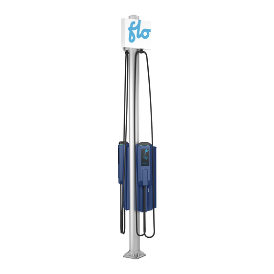
2.2. Specifications The SmartTWO-BSR is made of one dual pedestal, two SmartTWO charging stations and two cable management systems. Depending on the chosen configuration, the SmartTWO- BSR can also be provided with a Cellular Gateway. Cable management system Cellular Gateway (Master... -
Page 7: Dimensions
2.3. Dimensions The dimensions below apply to both Master and Auxiliary configurations of the SmartTWO- BSR. -
Page 8: Site Layout
3. Site Layout 3.1. Pedestal Positioning For each installation site, one master curbside pedestal should be installed, followed by auxiliary curbside pedestals (optional). The master curbside pedestal is equipped with a cellular LTE communication gateway that will link with up to 18 auxiliary unit charging stations (up to 9 pedestals) in close vicinity to the centralized network management server. -
Page 9: Concrete Base
Concrete Base – For Master Pedestals with an Integrated Electrical Distribution Panel When an electrical panel is installed on the back of the SmartTWO-BSR pedestal, it requires a separate conduit for the power input coming from the grid and going to the panel. The pedestal has a provision at the center of its base to let the power input pass from the concrete base up to the electrical panel. - Page 10 NOTE: The power input position for the integrated electrical distribution cabinet might vary. Validate that the cable can be routed correctly from the pedestal opening dedicated to the grid cabling conduit, to the position of the power input in the electrical distribution panel.
-
Page 11: Concrete Base - For Pedestals Without An Integrated Electrical Distribution Panel
3.2.2. Concrete Base – For Pedestals without an Integrated Electrical Distribution Panel This configuration is suitable for Auxiliary pedestals, and for Master pedestals without an integrated distribution panel. These configurations do not require grid power cables to be connected; therefore, the concrete base does not need a separate conduit to pass the grid cables. -
Page 13: Electrical Configuration
4.1. Power Input: Deported Electrical Distribution Panel These two configurations imply that the electricity is supplied by a deported electrical distribution panel that is not mounted on a Master SmartTWO-BSR pedestal. One conduit per pedestal is required to bring the cables to their respective pedestals. -
Page 14: 240V Split Phase Configuration
4.1.1. 240V Split Phase Configuration To feed each pedestal, two 240 V 40 A circuits (without neutral) are required to power the 208/240 V 30 A charging stations. In this case, only one conduit bringing all the cables in the center of the mast is required to feed the two charging stations installed on the pedestal. -
Page 15: 208 V 3-Phase Supplied By A Deported Electrical Distribution Panel
4.1.2. 208 V 3-Phase Supplied by a Deported Electrical Distribution Panel To feed each pedestal, two x 40 A phase to phase circuits (without neutral) are required to power the 208/240 V 30 A charging stations. We highly recommend evenly distributing the connections among the 3 phases in order to keep the load as balanced as possible. -
Page 16: Power Input: Integrated Electrical Distribution Panel
Electrical Distribution Panel section for more information. Number Description 2 to 3 inch (50.8 mm to 76.2 mm) conduit bringing the feeding cables from the grid directly into the integrated electrical distribution panel Integrated electrical distribution panel (Not provided by FLO) -
Page 17: 240 V Split Phase Configuration
4.2.1. 240 V Split Phase Configuration To feed each pedestal, two 240 V 40 A circuits (without neutral) are required to power the 208/240 V 30 A charging stations. In this case, a separate conduit is needed to bring the grid cable to the integrated electrical distribution panel. -
Page 18: Integrated Electrical Distribution Panel
The Master SmartTWO-BSR pedestal is designed with provisions to install an electrical distribution panel (Not provided by FLO) on its back. The latter can be installed directly at the back of the Master SmartTWO-BSR pedestal using the dedicated threaded anchor points, or on a fabricated rack designed to fit on the Master SmartTWO-BSR pedestal. -
Page 19: Anchor Points
5.2.1. Anchor Points The fabricated rack should have the following anchor point characteristic: Four anchor points with ¼-20 threaded inserts RECOMMENDATION: We recommend designing horizontal slotted holes to match the anchor positioning tolerances (5.8"± 1/8" or 147.32 mm ± 3.175 mm). -
Page 20: Installation
The electrical distribution panel should be installed securely on the pedestal using the fabricated rack. The opening for the conduits should be sealed properly. The next steps describe how to install the electrical distribution panel on the back of the Master SmartTWO-BSR pedestal: Access 2NPT1... - Page 21 2. Seal the electrical distribution panel to the pedestal. To do so, we recommend using the following parts: NOTE that depending on the chosen cabinet, the recommended parts might not be applicable. a. Standard-wall galvanized welded steel thread pipe nipple, 2 PIPE SIZE X 2" length, fully threaded: i.
-
Page 22: Electrical Installation
6. Electrical Installation 6.1. Lifting the Pedestal Follow the steps below to lift the pedestal safely and securely: Use a pole handling sling to lift the pedestal: put the pole handling sling around the pedestal only, avoiding charging stations and the cable management system. WARNING: ... -
Page 23: Pedestal Installation
1. If an integrated electrical distribution panel is used, make sure it is installed properly Integrated Electrical Distribution Panel on the SmartTWO-BSR pedestal. See the section for more information on the installation. 2. Insert the grid cable in the dedicated conduit in the concrete base. -
Page 24: Power Supply Cable Installation
3. Connect the grid cable to the integrated electrical distribution panel following manufacturer recommendations. Grid cable going to the integrated electrical distribution panel 6.4. Power Supply Cable Installation The power supply and ground cables (L1, L2, GND) must be inserted in the pedestals in order to connect them to the charging stations. -
Page 25: Deported Electrical Distribution Panel
6.4.1. Deported Electrical Distribution Panel Follow the steps below when power cables come from a deported electrical distribution panel: 1. Pass the power supply cables in the underground conduits and feed them inside the corresponding pedestal concrete base conduits. 2. Use the pedestal access door to reach inside the pedestal and pull the cables from the concrete base conduits. - Page 26 3. Feed all the cables mentioned above through the sealed opening between the integrated electrical distribution panel and the master pedestal. NOTE: Make sure the Master pedestal charging station cables are long enough to reach the charging station terminals, approximately 13.8’’ (350 mm) from the Master pedestal opening.
-
Page 27: Charging Station Connection
4. Feed the auxiliary pedestal charging station cables (L1, L2, GND) down into the Master pedestal concrete base conduit openings, (reach inside the pedestal through the access door opening to do so). 5. Feed the cables to the Auxiliary pedestals, making sure they are long enough to reach the charging station terminals;... -
Page 28: Pedestal Panel Removal
6.5.1. Pedestal Panel Removal 1. Remove the pedestal front panels by unscrewing the two screws on each charging station and sliding the panels towards the top. Remove screws Slide panels up 2. Remove the protection panels by unscrewing the four screws on each charging station and pulling gently on the top of the panel. -
Page 29: Charging Station Cable Routing And Ground Connection
The electrical components and the charging station conduit openings will become accessible. Charging station conduit openings 6.5.2. Charging Station Cable Routing and Ground Connection The feeding cables can come either from the back or bottom of the pedestal depending on if an integrated or deported electrical distribution panel is installed. - Page 30 2. Pull the master pedestal ground wire (GND) coming from the integrated electrical distribution panel ground bar towards the pedestal access door. Charging station cables (L1, L2, GND) Charging station conduit openings Master pedestal ground wire (GND) Access door location 3.
- Page 31 Cable Coming from the Bottom of the Pedestal 6.5.2.2. Follow the steps below for installations with cables coming from the bottom of the pedestal: 1. Pull the ground wire coming from the concrete base towards the pedestal door opening. 2. Connect the ground wire on the pedestal ground bar using a 40 in-lbs / 4.5 N.m torque.
-
Page 32: Charging Station Wire Connection
6.5.3. Charging Station Wire Connection Follow the steps below for every charging station: 1. Tighten the ground cable (GND) to the ground terminal using a 30 lbs-in / 3.4 Nm torque. 2. Tighten the power cables (L1, L2) to the electrical terminal bloc using a 40 lbs- in / 4.5 Nm torque. -
Page 33: Charging Station Installation
7. Charging Station Installation Once the electrical connection is completed, re-install the protection panels and the charging station, and complete the preliminary tests. 7.1. Pedestal Access Door Installation Follow the step below to install the access door: 1. For each pedestal, close the pedestal and tighten the screws using a 10N*m or 80 lbs-in torque. - Page 34 2. Install the front panels by sliding them down and tightening the two screws using a 10Nm or 80 lbs-in torque. Remove Screws Slide panels down...
-
Page 35: Charging Station And Connector Installation
7.3. Charging Station and Connector Installation NOTE that the numbers in brackets in the text refer to the material in the image. Installation of the charging station on its base Unscrew the charging port holder (4). 2. Remove the charging port and cable assembly: a. -
Page 36: Preliminary Tests And Commissioning
7.4. Preliminary Tests and Commissioning Instructions Place the charging port in the holder and close the door (1 and 2). Once the charging station is powered up, check the following: The door is locked. The charging station status lights turn GREEN. The display shows the greeting messages. -
Page 37: Preliminary Tests And Commissioning
If not, 1 minute later, the charging session will be cancelled. 4. If the preliminary test is successful: a. Make sure you have installed the Communication Gateway according to the Communication Gateway Installation Guide instructions described in the , if necessary. b. Call FLO for charger commissioning: 1-855-543-8356... -
Page 38: Copyright And Liability
Name: FLO_SmartTWO-BSR_Installation Guide_V.1.0.0_2023-01-27_US_EN Document ID: PRFM0052 FLO US: © 2023 FLO Services USA Inc., All rights reserved. FLO, the FLO logo, LEAD THE WAY, and TRACEZ LA VOIE are trademarks of Services FLO Inc. used under license by FLO Services USA Inc. - Page 39 Contact us Telephone: 1 855 543 8356 Email: Info@flo.com Website: Flo.com Eastern office: 2800, Louis-Lumière Street, office 100, Québec, QC, Canada - G1P 0A4 Regional office – Western Canada: #501 – 4190 Lougheed Highway, Burnaby, BC, Canada - V5C 6A8...
Need help?
Do you have a question about the SmartTWO-BSR and is the answer not in the manual?
Questions and answers