Advertisement
Quick Links
Advertisement

Subscribe to Our Youtube Channel
Related Manuals for Flo Ultra FL1SS1B1AA Series


Summary of Contents for Flo Ultra FL1SS1B1AA Series
- Page 1 FLO Ultra™ Installation Guide ...
-
Page 2: Table Of Contents
2.3. Safety Symbols on your Product 2.4. FCC Statement 2.4.1. Supplier's Declaration of Conformity 47 CFR 2.1077 Compliance Inform- ation 2.5. Industry Canada Compliance 3. Introduction 3.1. About FLO Ultra 3.2. About this Guide 4. Specifications 5. Site Preparation 5.1. Site Configuration 6. Typical Installation 6.1. - Page 3 7.5. Lifting 7.5.1. Center of Gravity 7.6. Hoist Lifting 7.7. Forklift Lifting 7.7.1. Installing the Lifting Jig on the FLO Ultra 7.7.2. Lifting the FLO Ultra with a Forklift 8. Box Contents 9. Additional Required Parts 10. Additional Recommended Parts (Optional) 11.
- Page 4 16.6.2. Sticker Order 16.6.3. Application Method 16.7. Installing the Banner 16.8. Installing the Screw Caps on Top of the FLO Ultra 16.9. Installing the Charging Cable Clamp 17. Installing the Protective Plate on the Electrical Compartment 18. Installing the Lower Panels 19.
- Page 5 21.1. General Exterior Maintenance 21.2. Banner Sticker Cleaning 21.3. Cabinet Cleaning 21.4. Visual Inspection of the Cabinet 21.5. Removing Graffitti 21.5.1. Cleaning the Enclosure 22. Copyright and Liability...
-
Page 6: Instructions Pertaining To A Risk Of Fire Or Electric Shock
SAVE THESE INSTRUCTIONS. WARNING – When using electric products, basic precautions should always be followed, including the following. This manual contains important instructions for all FLO Ultra™ models that shall be followed during installation, operation, and maintenance of the unit. ... - Page 7 14. Class 1 wiring methods are to be used for field wiring connections to terminals of a Class 2 circuit (Ethernet or control signal). 15. Ensure compliance to specific Bonding/Grounding instructions for the FLO "Grounding Instructions for Products with a Permanent Power Ultra™.
-
Page 8: Important Safety Instructions
5. FLO cannot be held responsible for any damage that may occur resulting from custom installations not described in this document. 6. If for any reason it is not possible to install the FLO Ultra according to the procedures provided in this guide, the installer should contact the FLO team. - Page 9 14. Ensure that the upstream disconnect is in the open position and follows workplace electrical safety procedures, as required by the local jurisdiction. 15. In the event of an earthquake in the region, the FLO Ultra charging station must undergo a detailed inspection by a certified technician before being put back into service.
-
Page 10: Responsibilities
5. Make sure the FLO Ultra charging station is installed for use with all the protective devices and equipment, as indicated in this guide, and according to the local jurisdiction. -
Page 11: Installer Responsibilities
User Guide available on hand during the installation process and all maintenance activities. 3. Be fully prepared on the details of the site, the FLO Ultra charging station and how to complete a safe installation on the specific site. 4. Make sure the FLO Ultra charging station is installed for use with all the protective devices and equipment, as indicated in this guide, and according to the local jurisdiction. - Page 12 5. Make sure the FLO Ultra charging station is installed for use with all the protective devices and equipment, as indicated in this guide, and according to the local jurisdiction. 6. Make sure that all protective measures for use are in effect after installation and after all maintenance work, according to this guide and local jurisdiction.
-
Page 13: Safety Symbols On Your Product
2.3. Safety Symbols on your Product The symbols in the table below may be present on your charging station and in this guide. Please refer to the table below for information on the symbols. Symbol Description Alternating current (AC) Direct current (DC) Phase CAUTION: This symbol is used to provide awareness of important safety information in these instructions... -
Page 14: Fcc Statement
2.4. FCC Statement FCC Statement (for USA only) This equipment has been tested and found to comply with the limits for a Class B digital device, pursuant to Part 15 of the FCC Rules. These limits are designed to provide reasonable protection against harmful interference in a residential installation. -
Page 15: Supplier's Declaration Of Conformity 47 Cfr 2.1077 Compliance Information
2.4.1. Supplier's Declaration of Conformity 47 CFR 2.1077 Compliance Information Unique Identifier: FLO Ultra™ Model Numbers FL1SS1B1AA-XX-XXX FL1SS2B1AA-XX-XXX FL1SS1A1AA-XX-XXX FL1SS2A1AA-XX-XXX FL1DS1A1AA-XX-XXX FL1DS2A1AA-XX-XXX NOTE: The X's in the table above represent the colors of the models. X's have been used in order to add to the color range in the future. -
Page 16: Industry Canada Compliance
2.5. Industry Canada Compliance This device complies with Industry Canada license-exempt RSS standard(s). Operation is subject to the following two conditions: (1) this device may not cause interference, and (2) this device must accept any interference, including interference that may cause undesired operation of the device. Le présent appareil est conforme aux CNR d’Industrie Canada applicables aux appareils radio exempts de licence. -
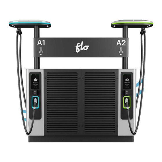
Page 17: Introduction
The FLO Ultra has the capacity to charge up to 80% in as little as 15 minutes with a 320 kW total capacity (160 kW on each side). -
Page 18: About This Guide
FLO Ultra including the unpacking, moving, lifting, site preparation, final assembly and commissioning. This guide will provide you with information about the FLO Ultra and its components, guide you through the installation of a station on a particular site, and provide you with general information about upkeep and support. -
Page 19: Specifications
≈ 408 A Integrated protection IM/I, GM/I Power consumption 337 kVA 320 kW (2 x 160 kW) FLO Ultra can be paired Max output power to deliver up to 500 kW to a vehicle Input rating 480 Y-277 V (-15% to 10%) - Page 20 Specification Description English, French, Spanish Charging station status LED indicators Vehicle state of charge LED indicators Standard card reader: tap (NFC, insert, Credit card reader swipe) RFID user authentification ISO 14443A/B, ISO 15693, HID, MiFare DIN-SPEC 70121, ISO 15118-2 (tested under Charging protocol ISO 15118-4-5) Connectivity...
- Page 21 Specification Description Standard cable length 18' (5.5 m) CCS 1 Charging connector IEC 62196 FLO EZLift™ motorized cable management Cable Management System (CMS) (standard) ...
-
Page 22: Site Preparation
5.1. Site Configuration The FLO Ultra user interface can be located on either side of the charging station or on the same side to support the pull-in or pull-through parking configurations. The following image shows the pull-in parking installation:... - Page 23 The following image shows the pull-through parking installation:...
-
Page 24: Typical Installation
Outlet 1 - Pairing control and communication conduits / conductors (optional) Outlet 1 - 1000 VDC conduits/conductors (optional) FLO Ultra control and communication conduits / conductors (optional) 3-phase, 3-wire 480Y / 277 VAC conduits/conductors Outlet 2 - 1000 VDC conduits/conductors (optional) -
Page 25: Charging Station Dimensions
6.1. Charging Station Dimensions Ensure that the selected site is large enough to house the FLO Ultra charging station. Refer to "Surface Area Requirements" on page 32 "Reach of the Charging Station Connectors" on page 33 for more information. The image below shows the FLO Ultra charging station dimensions:... -
Page 26: Main Exterior Components
6.2. Main Exterior Components The image below shows the FLO Ultra charging station's main exterior components: Part Description Banner Main compartment doors Canopy Charger status light indicator Cable clamp FLO EZLift Canopy area lighting Charging station identifier Charging cable User interface touchscreen... -
Page 27: Height Of Operable Parts
American Disability Act's (ADA) standard for accessibility. Compliance with the ADA requirements is subject to site design and installation which are the responsibility of the installers. See the image below for the interaction heights of the various FLO Ultra components: Part... -
Page 28: Mounting Pad
6.4. Mounting Pad The mounting pad is a concrete slab on which the FLO Ultra is installed. Follow the installation guidelines below to ensure the correct installation of the mounting pad and the FLO Ultra: The FLO Ultra must be installed on a concrete mounting pad. - Page 29 IMPORTANT NOTE: The height of the 4 threaded anchors (A) should rise 3″ (76.2 mm) above the FLO Ultra surface mount and have a diameter of ¾″ (19.1 mm). The conduits should rise 1.77'' (45 mm) above the FLO Ultra surface mount to enter...
- Page 30 the terminals. Refer to "Connecting the AC Power Cables" on page 76 for more information. NOTE: Please refer to the site assessment requirements and anchor supplier’s recommendation for the selection of the anchors. The power cable compartment and lug pad dimensions are detailed in the side-view images below: ...
- Page 31 Side View of the AC Power Connections Side View of DC Power Connections (If Applicable)
-
Page 32: Surface Area Requirements
6.6. Surface Area Requirements The minimum required clearance for the maintenance and operation is indicated in the top view image below. Zones A, B and C should be free of obstacles. NOTE: Additional space may be required to meet the ADA requirements. ... -
Page 33: Reach Of The Charging Station Connectors
6.7. Reach of the Charging Station Connectors The reach of the charging station connectors must be taken into consideration when planning the site installation. The image below shows the reach of the FLO Ultra charging station connectors: NOTE: Protective barriers, such as wheel stops and low-height bollards, can also be used. -
Page 34: Compartment Access
6.8. Compartment Access Follow the instructions in the sections below to access the UI compartment, the main electrical compartment, and the electrical cable compartment. Part Description User interface compartment (left, front access) Main electric compartment User interface compartment (right, front access) Power cable compartment User interface compartment (left, rear access) Rear compartment... -
Page 35: Accessing The Door Compartments
6.8.1. Accessing the Door Compartments Each of the user interface doors, and outer main compartment doors is locked with a two-latch locking mechanism. The inner electric compartment doors are equipped with a latch closing mechanism. The image below shows the location of the latch locks of the outer door-accessible compartments: ... - Page 36 The image below shows the inner electrical compartment door latches: Part Description Inner electrical compartment door latch (upper left) Inner electrical compartment door latch (lower left) Inner electrical compartment door latch (upper right) Inner electrical compartment door latch (lower right)
- Page 37 The image below shows a zoomed in view of the door accessible compartments when the outer main compartment door and user interface doors are open: NOTE: The user interface doors must first be open in order to open the outer main compartment doors.
-
Page 38: Engaging The Door Stays
To access any of the latch-lock compartments listed follow the steps below: 1. Insert the key provided with the FLO Ultra in the latch-lock and turn it 90 degrees counterclockwise. 2. Repeat the action for any other latch-lock on the doors you want to open. - Page 39 To keep the inner electric compartment doors open, open the doors to the fullest extent and push the doors into the outer main compartment doors until the plungers at the top of the outer doors engage in the inner door holding brackets. ...
- Page 40 To close the outer main compartment doors and engage the door stays, push the doors into the charging station until the plungers at the top of the outer doors engage in the charging station holding brackets. Part Description Inner door plunger Charging station holding brackets...
-
Page 41: Moving And Storing Instructions
1. Only trained and certified workers may operate a forklift. 2. Ensure operators are trained on the types of trucks used for moving the charger. FLO recommends following the guidelines below to move the crate safely with a forklift: ... -
Page 42: Unloading The Crate From The Truck
Dimensions: 132 x 48 x 90 inches (335 x 122 x 229 cm) Lifting modes: The FLO Ultra must be picked up by the forklift from one of the two long sides. NOTE: Forklift extensions are required to handle the crate from the long side. -
Page 43: Moving The Crate Safely
7.4. Moving the Crate Safely FLO recommends that you follow the guidelines below to handle the box safely with a forklift: ... -
Page 44: Uncrating The Charging Station
7.4.1. Uncrating the Charging Station Follow the instructions below to remove the charging station from the shipping crate: Refer to the image below for panel identification: ... - Page 45 1. Remove the following 28x screws from the crate: a. 4x screws on top of the crate. b. 4x screws on back side assembly panel 5 and back side assembly panel 7. c. 4x screws on front side assembly panel 2 and front side assembly panel d.
- Page 46 4. Remove top panel with batten assembly 8 by following the steps below: a. Remove the 8x screws from the end and 2 side panels. b. Remove top panel with batten assembly 8 carefully and place it out of the way.
- Page 47 7. Remove back side assembly panel 5 by following the steps below: a. Remove the 2x screws from the bottom of the panel. b. Remove the 4x screws from the side of the panel. c. Remove left side wall panel 5 carefully and place it out of the way. 8.
- Page 48 9. Remove center front side assembly panel 3 by following the steps below: a. Remove the 2x screws. b. Remove center front side assembly panel 3 carefully and place it out of the way. 10. Remove right side wall panel 2 by following the steps below: a.
- Page 49 11. Remove right end panel 1 by following the steps below: a. Remove the 2x screws from the bottom of the panel. b. Remove right end panel 1 carefully and place it out of the way. 12. Remove the fasteners from around the 3 boxes (ASAC0001, ASAC0002 and ASAC0003) attached to the pallet.
- Page 50 14. Remove the banding strap by feeding it through the (PAWT0193) slot. 15. Remove the (PAWT0200) padding and (PAWT0202) protector from the top of the charging station. 16. Remove the (PAWT0197) padding from the top of the UI doors. 17. Remove the (PAWT0203) padding from the door.
- Page 51 18. Remove the (MEDS1089) door brace under the UI door by unscrewing the screw. 19. Remove the plastic banding on both sides of the charging station that holds the door padding in place and the handle and hinge padding as well. 20.
- Page 52 22. Open the outer right compartment door to remove the (PAWT0196) padding inside at the top. 23. Remove the (PAWT0198) padding from the (MEDS1087) brace. 24. Remove the (MEDS1087) lower shelf brace by unscrewing the 2x (MESB0131) screws using a 10 mm socket wrench. 25.
- Page 53 26. Remove the zip ties securing the canopy protective padding in place. 27. Remove the (PABX0049) piece of cardboard placed under the AC power cables. 28. Perform a visual check on the charger looking for any scratches or dings. 29. Keep the cables tied until after the AC and DC power cables are completed. Refer to "Unpacking the Charging Cables"...
-
Page 54: Lifting
7.5. Lifting The FLO Ultra includes a hoist attachment or an optional forklift attachment to assist with the handling. 7.5.1. Center of Gravity The images below show the FLO Ultra's center of gravity. -
Page 55: Hoist Lifting
NOTE: Hoist lifting is the recommended lifting method. WARNING – Keep a security perimeter around the hoist and under the FLO Ultra during transportation. Do not stand under the FLO Ultra during transportation. The hoist lifting procedure uses screw eye hooks with an inside measurement of 3/4'' (19 mm) provided by FLO. - Page 56 6. Lift the FLO Ultra and transport it to the correct location. Avoid abrupt turns, stops and starts 7. Gently place the FLO Ultra at the correct location making sure to pull the AC and DC cables through the frames of the lower electric connection...
- Page 57 8. Unfasten the charging station from the forklift, remove the strap and then retract the forklift forks.
-
Page 58: Forklift Lifting
7.7. Forklift Lifting NOTE: The Forklift Lifting section is only applicable when you are moving the FLO Ultra with a forklift. NOTE: The lifting jig (ASME0586) is optional and sold separately from the FLO Ultra charging station. Please refer to the FLO Ultra Ordering Guide available at flo.com. - Page 59 1. Place the forklift lifting jig horizontal bars on top of the FLO Ultra, aligning the extrusions at the bottom with the indentations on top of the FLO Ultra. 2. Place the angle lift lifting jigs on top of the forklift lifting bars in a perpendicular arrangement, aligning the screw holes of the angle lifting jigs and the lifting bars.
- Page 60 3. Place the washer on top of the angle lift lifting jig screw hole and screw in the head screw. On the bottom of the angle lift lifting jig, add an oversized washer and a bolt to the head screw to secure the parts together. The torque must be 70 N m (51.6 lb-pi).
-
Page 61: Lifting The Flo Ultra With A Forklift
3. Confirm the lifting capacity of the forklift to make sure it can safely lift the weight of the FLO Ultra. Only use a forklift that can safely lift the FLO Ultra. The lifting capicity of the forklift must be over 700 kg (1 540 lbs) to lift the charging station and the lifting jig. - Page 62 6. Ensure the good positioning of the forks between the forklift lifting jig and the FLO Ultra (identified by each of the arrows of B). Do a visual check to ensure the right positioning of the forks and that the path of the forklift is clear.
-
Page 63: Box Contents
Description Quantity Box Number Number MEDS0739 Lower post support MEDS0740 Internal banner support MEDS0701 FLO Ultra banner support MEDS0700 FLO Ultra banner AC power cable entry plate MEDS0934 and 4 self tapping screws MEDS0805 DC power cable entry plate MEDS0741... - Page 64 Protective corners, right MEDS1079 Protective corners, left MESB0368 Screws for protective corners PRLP1096 Identification stickers (letter A) PRLP1097 Identification stickers (letter B) MEDS1082 Access key PRFM0100 FLO Ultra Installation Guide - English PRFM0101 FLO Ultra Installation Guide - French TOSR0208 Plastic squeegee...
-
Page 65: Additional Required Parts
Control Wiring " on page 82 sections for more information. 10. Additional Recommended Parts (Optional) FLO recommend using the following parts to complete the installation of the FLO Ultra. Part Forklift lifting jig (ASME0586) Soft cloth Neutral cleaning agent (without ammonia) Ethernet cables ... -
Page 66: Installation Instructions
United States. The installation shall be in accordance with the Canadian Electrical Code, Part I. (ref: CSA C22.2 no.107.1 art.5.26) for products installed in Canada. Follow the steps in the sections below to complete the FLO Ultra installation: ... -
Page 67: Grounding Instructions For Products With A Permanent Power Connection
11.1. Grounding Instructions for Products with a Permanent Power Connection Products with a permanent power connection must follow the instructions below: This product must be connected to a grounded, metal, permanent wiring system, or an equipment grounding conductor must be run with the circuit conductors and connected to the equipment grounding terminal or lead on the product. -
Page 68: Recommended Tools
11.2. Recommended Tools The tools in the following table are not provided by FLO but we recommend using them to complete the FLO Ultra installation: Installation Tools Process Drill #2 square drive bit Uncrating the FLO Ultra Ratchet with 15/16" deep socket (or wrench) - Page 69 Installation Tools Process Ratchet with 13 mm socket (or wrench) Torque wrench with 13 mm socket Raising posts Post lifting tool Torque wrench with 10 mm socket Installing post cover brackets Ratchet with 17 mm socket (or wrench) Removing the lifting structure Cover holes with screw cap Torque wrench covers...
-
Page 70: Securing The Flo Ultra To The Concrete Slab
NOTE: The concrete slab must be level to ensure correct installation. 1. Insert a nut and washer (not provided by FLO) on each anchor (4x) and adjust the height of the nut to accommodate the leveling of the FLO Ultra. There must be exactly 1 3/16'' (30 mm) between the washer and the concrete slab. - Page 71 2. Lift the FLO Ultra, following the hoist or forklift instructions, as applicable, and align the base mounting holes with the anchors (4x). WARNING: Ensure a safety perimeter under and around the hoist and supended FLO Ultra. Make sure no people are in the vicinity of the suspended charger.
- Page 72 3. Slowly lower the station, aligning the FLO Ultra mounting holes (4x) with the anchors until the FLO Ultra rests on the washers/nuts (4x).
- Page 73 4. Insert the washers and nuts, then loosely fasten the nuts (4x), leaving sufficient space to adjust the height of the nuts to level the FLO Ultra, as detailed in the next step. ...
- Page 74 5. Level the FLO Ultra by adjusting the height of the nuts to ensure the lowest flat washer is at a height of 1 3/16'' (30 mm) to maintain sufficient space between the base of the FLO Ultra and the concrete slab for the installation of the side, rear and front lower panels after the power cable connection.
-
Page 75: Power Module Verification
6. Tighten the nuts (4x) according to anchors' recommended specifications to secure the FLO Ultra on the concrete slab. NOTE: For more information, please refer to the FLO UL Ultra Site Planning Application Note , provided by request to installers. -
Page 76: Connecting The Ac Power Cables
12. Connecting the AC Power Cables 1. Punch holes in the AC power cable entry access plate (MEDS0934) to match the size and locations of the conduits. 2. Use the tables below as a reference for the AC electrical input connection (L1, L2, L3). - Page 77 Conductor terminals (lugs) (appropriate size according to conductor size), one for each AC conductor termination in each FLO Ultra on site. RECOMMENDATION: FLO recommends the use of a dieless cable crimping tool kit to making crimping the cables easier.
- Page 78 Conduit Recommendations Table Typical conduit size for AC conductors 4'' (102 mm) Typical conduit size of control and communication cables 1'' (25 mm) (Ethernet upstream and other small cables) AC input 3. Pull the cables through the power cable entry access plate (MEDS0934) openings and place the power cable entry plate back in its position.
- Page 79 4. Tighten the screws (4x) (MESB0368) to secure the power cable entry plate. 5. Seal the area surrounding the conduits and the gap between the conductors in the conduits.
- Page 80 6. Connect the L1, L2, L3 cable conductor terminals (lugs) (up to 2 lugs per phase) to the incoming AC terminal busbars. NOTE: Follow local regulations when choosing your number of conductor terminals (lugs). Part Description Belleville washer Washer Compression lug AC terminal busbar Head screw...
- Page 81 7. Place the washers, the belleville washers with the concave side towards the busbar, and the bolts on either side of the compression lugs. NOTE: The belleville washers must be placed correctly to ensure a correct installation. 8. Tighten the nuts in accordance with the lug manufacturer torque recommendation.
-
Page 82: Connecting The Optional Dc Power Cables And The Control Wiring
13. Connecting the Optional DC Power Cables and the Control Wiring 1. Punch holes in the DC power cable entry access plate (MEDS0805) to match the size and locations of the power and optional control conduits. NOTE: In order to accommodate future power sharing capabilities on stations with the DC input option, you must cut out three holes in the access plates (MEDS0805) to accommodate the additional cables during the installation process. - Page 83 3. Tighten the screws (MESB0368) (4 per plate) to secure the cable entry plates, one on each side. 4. Seal the area surrounding the conduits and the gap between the conductors and the conduits.
- Page 84 5. Use the table below as a reference for the DC electrical bus connection (DC+ and DC-). DC+ and DC- Wire Specifications and Connection Table Number of conductors 2 per line Size of the conductors 4/0 AWG – 700 MCM, 120 mm –...
- Page 85 RECOMMENDATION: FLO recommends the use of a dieless cable crimping tool kit to crimp the cables. Part Description Belleville washer Washer Compression lug DC terminal busbar Head screw...
- Page 86 6. Connect the DC+ and DC- cable lugs (up to 2 lugs per phase) to the incoming DC terminal busbars. 7. Place the washers, the belleville washers with the concave part towards the busbar, and the bolts on either side of the compression lugs. 8.
- Page 87 9. Connect the wires (3 twisted pairs) to the 3 terminal blocks and the RJ45 communication cable of each paired charger (2x). NOTE: Reverse the polarity of the conductors (3 twisted pairs) wired to the terminal blocks of the paired chargers as detailed in the pairing wiring diagram below. NOTE: This harness can be built using unshielded twisted-pair cables.
- Page 88 Terminal Block Table From Charger 1 To Charger 2 Wire Connections TB1 or TB3 TB1 or TB3 ...
- Page 89 ...
-
Page 90: Nameplate Labels On Your Charger
14. Nameplate Labels on your Charger The following nameplate labels indicating essential information, such as model, brand and number, safety information and critical specifications, including voltage and amperage data are on your charger. 14.1. Nameplate Label with DC Input Refer to the image below for information on the nameplate label with DC input. -
Page 91: Nameplate Label Without Dc Input
14.2. Nameplate Label without DC Input Refer to the image below for information on the nameplate label without DC input. 14.3. Nameplate Label on a Multi-Unit Charger with DC Input Refer to the image below for information on the nameplate label for a multi-unit charger installation with DC input. -
Page 92: Amperage Value Sticker
14.4. Amperage Value Sticker The table below shows the amperage the charging station pulls and the corresponding total power that is available as output. Using the provided label sheet (PRIP1103), select and install the appropriate value onto the nameplate label, according to the site configuration: Amperage Total Power... -
Page 93: Unpacking The Charging Cables
15. Unpacking the Charging Cables Follow the steps below to unpack the cables. 1. Remove the tie-rap tying the cables to the lifting jig (shown in orange). 2. Unwrap charging cables around the canopy on the top of the charger and through the openings of the foam. -
Page 94: Raising The Canopy
16. Raising the Canopy The following sections detail the steps involved in installing the canopy. The canopy contains the following components: Part Description Canopy - Left side Pole mounting brackets On-site installation kit Tightening nut Fastening bolt ... -
Page 95: Removing The Brackets And The Lifting Jig
16.1. Removing the Brackets and the Lifting Jig Follow the instructions below if you have installed an accessory or lifting jig: 1. Remove the forklift lifting jig (ASME0586), if applicable. 2. Unscrew the bolts (2x) securing the front lifting bar and remove it. Repeat the operation for the rear lifting bar. -
Page 96: Lifting The Canopy
16.2. Lifting the Canopy NOTE : At least two people must complete the Lifting the Canopy step. Follow the steps below to lift the canopy safely: 1. Unscrew the bolts (A) (4x) until you can insert the lifting wedges (B) (4x). 2. - Page 97 3. Insert the lifting tool (C) (MEDS0741) into the extrusion, taking care to position the power cable (D) correctly. ...
- Page 98 4. Raise the canopy until the 2 latches (M) click into place.
- Page 99 NOTE: The 2 latches must be correctly engaged. 5. Remove the canopy lifting tool (F in the image above).
-
Page 100: Assembling The Cover Support
16.3. Assembling the Cover Support Follow the steps below to assemble the cover support: 1. Insert the lower support (G)(MEDS0739) into the grooves on the post. 2. Tighten bolts (I) (2x)(MESB0311) to 10 N m. - Page 101 3. Insert the middle support (J) (MEDS0740) into its grooves. 4. Tighten bolts (L) (MESB0311) (4x) to 10 N m.
-
Page 102: Complete The Final Positioning Of The Canopy
16.4. Complete the Final Positioning of the Canopy Refer to the images and table below for more information on the parts: 1. Lift and hold the 2 latches (M) to unlock them. - Page 103 2. Lower the canopy so that the lower support (N) (MEDS0739) rests completely on the plastic part (O).
- Page 104 3. Lower the canopy so that the lower support (N) (MEDS0739) rests completely on the plastic part (O).
- Page 105 4. Lower the canopy so that the lower support (N) (MEDS0739) rests completely on the plastic part (O). 5. Slightly loosen the 4 bolts (P) and pull out the 4 spacers (Q) completely.
- Page 106 6. Insert the 2 tension bolt assemblies (R) (MESB0343, MEWS0096 and MEDS0734). 7. Tighten both tension bolts to 3 N m. 8. Tighten the 4 support bolts (P) gradually and evenly to 16 N m.
-
Page 107: Assembling The Canopy Pole Covers
16.5. Assembling the Canopy Pole Covers Follow the steps below to assemble the canopy pole covers: 1. Slide on the two covers (S and T) (MEDS0736 and MEDS0737), ensuring that the 4 fastening holes (U) face the inside of the charging station. - Page 108 2. Partially insert the 6 screws (N) (MESB0315). 3. Tighten the 6 screws (N) to 5 N m. 4. Repeat steps 1 to 3 for the other canopy. NOTE : Make sure you have positioned the left and right canopy pole covers correctly before proceeding to the next step.
-
Page 109: Installing The Letter Stickers On The Banner
16.6. Installing the Letter Stickers on the Banner Follow the instructions below to apply the letter stickers on the banner. FLO recommends the following guidelines to ensure a successful application: Use the following required tools: Application squeegee (TOSR0208) for applying the sticker ... - Page 110 Sticker Placement on a Pull-In Configuration Sticker Placement on a Pull-Through Configuration ...
-
Page 111: Application Method
16.6.3. Application Method Follow the steps below to apply the stickers correctly: 1. Place the banner on a flat stable surface to install the stickers (PRLP1096 or PRLP1097). 2. Using the hinge method, peel back the sticker liner about 40 mm or 1 ½'', exposing the adhesive, and fold back the liner. -
Page 112: Installing The Banner
16.7. Installing the Banner 1. Align the banner supports (2x) (MEDS0701) with the banner studs (4x) and loosely fasten the nuts (4x) (MENU0071). 2. Insert and loosely fasten the banner support screws (8 screws; 4 on each side) (MESB0312) into the banner brackets. - Page 113 3. Hook the rear banner to the bracket screws (2 on each side). 4. Tighten the screws (4x) (MESB0312) with a torque of 6 N m, tighten the nuts (4x) (MENU0071) with a torque of 6 N m.
- Page 114 5. Repeat the steps for the front banner.
-
Page 115: Installing The Screw Caps On Top Of The Flo Ultra
16.8. Installing the Screw Caps on Top of the FLO Ultra Follow the instructions below to install the screw caps (ASME0638) on the holes left by the lifting jig: 1. Locate the holes left by the removal of the lifting jig. - Page 116 2. Place the (4x) screw caps in the holes on top of the charging station. 3. Use the spanner head or Hafren two-hole security screw drive bit (MEHD0540) to tighten the two-hole security screw.
- Page 117 4. Make sure not to over tighten the screws. ...
-
Page 118: Installing The Charging Cable Clamp
16.9. Installing the Charging Cable Clamp Follow the steps below to install the cable clamp on the bottom of the FLO Ultra canopy: 1. Pull the FLO EZLift wire from the canopy towards you to ensure a good grip. 2. Insert the round end of the cable wire into the cable clamp. -
Page 119: Installing The Protective Plate On The Electrical Compartment
17. Installing the Protective Plate on the Electrical Compartment The protective panels seal the electrical compartment from the outside elements. Follow the steps below to install the protective plate on the electrical compartment: 1. Open the main doors before installing the protective panels. 2. - Page 120 3. Insert the screws and tighten to torque, making sure not to over-tighten.
-
Page 121: Installing The Lower Panels
18. Installing the Lower Panels The lower panels seal the electrical compartment from the outside elements. Follow the steps below to install the lower panels: 1. Open all the doors before installing the lower panels, including the main doors and the UI doors. 2. - Page 122 4. Loosely fasten the panel to the FLO Ultra base with the screws (MESB0280 and MEDS0796). Do not tighten the screws at this stage. 5. Repeat steps 1-3 with the back lower panel. 6. Repeat steps 1-3 with the side panels.
- Page 123 7. Tighten the screws making sure not to over tighten.
-
Page 124: Adding The Protective Corners
Follow the steps below in order to install the protective corners: 1. Make sure the FLO Ultra is in its final position and that the bottom plate and lower panel have been correctly installed. 2. Open the UI doors. - Page 125 5. Once the protective corner (MEDS1079) is in place, use the provided self tapping screws (MESB0368) to fasten it in place. Do not over tighten the screws over 4 N m. 6. Align the protective corner labeled MEDS1078 over the side of the charger, making sure that the shorter side of the corner is on the side of the charger and that it overlaps over the already installed MEDS1079 protective corner.
- Page 126 7. Once the MEDS1078 protective corner is in place, use the provided self tapping screws (MESB0368) to fasten it in place. Do not overtighten the screws over 4 N m. 8. Repeat steps 1-7 on the other side of the changer, beginning with the front of the charger this time.
-
Page 127: Commissioning
20. Commissioning To ensure easy and efficient commissioning, please consult the FLO Commissioning Guide , and make sure you have all the information you need before contacting FLO customer service. Please refer to the instructions in this document for submitting the form and photos. -
Page 128: User Maintenance Instructions
21. USER MAINTENANCE INSTRUCTIONS We recommend that station owners perform the following maintenance. All other maintenance activities must be performed by FLO technicians or by qualified service personnel mandated directly by FLO. 21.1. General Exterior Maintenance FLO recommends regular cleaning of the charging station to avoid potential accumulation of dirt, debris, dust or snow on the unit and the concrete mounting pad. -
Page 129: Visual Inspection Of The Cabinet
21.4. Visual Inspection of the Cabinet Make sure the following components are exempt of damage: General structural integrity: No slanting, no missing parts. no visibly obvious damage. EV charge cables: No cracks or ruptures, no visible internal wires. ... -
Page 130: Removing Graffitti
21.5. Removing Graffitti Follow the instructions in the sections below to remove the graffitti: 21.5.1. Cleaning the Enclosure Use the cleaning method adapted to the surface: Painted Surface: A neutral cleaning agent (ph 6 to 8) such as soapy water or 70% alcohol isopropyl with microfiber towel. -
Page 131: Copyright And Liability
Document Name: FLO_FLO Ultra_Installation Guide_V.1.0.0_2024-10-23 _CA_US_ Document ID: PRFM00100 FLO CA: © 2024 Services FLO Inc., All rights reserved. FLO, the FLO logo, LEAD THE WAY, and TRACEZ LA VOIE are trademarks of Services FLO Inc. ADDÉNERGIE is a trademark of AddÉnergie Technologies Inc. used under license by Services FLO Inc. - Page 132 Eastern office: 2800, Louis-Lumière Street, office 100, Québec (QC) G1P 0A4 CANADA Regional office – Western Canada: #501 – 4190 Lougheed Highway Burnaby (British Columbia), Canada, V5C 6A8 United-States Office: 1270 Pacific Dr, Auburn Hills, MI, United States – 48326...
Need help?
Do you have a question about the Ultra FL1SS1B1AA Series and is the answer not in the manual?
Questions and answers