TE Connectivity PRO-CRIMPER III Instruction Sheet
Hand crimping tool
Hide thumbs
Also See for PRO-CRIMPER III:
- Instruction sheet (11 pages) ,
- Assembly instructions manual (8 pages) ,
- Manual (7 pages)
Table of Contents
Advertisement
Quick Links
PROPER USE GUIDELINES
Cumulative Trauma Disorders can result from the prolonged use of manually powered hand tools. Hand tools are intended for occasional use
and low volume applications. A wide selection of powered application equipment for extended-use, production operations is available.
Locator Assembly
Additional Contact Support
Stationary Jaw
Die Assembly
Moving Jaw
Die Retaining Screw
(2 Places)
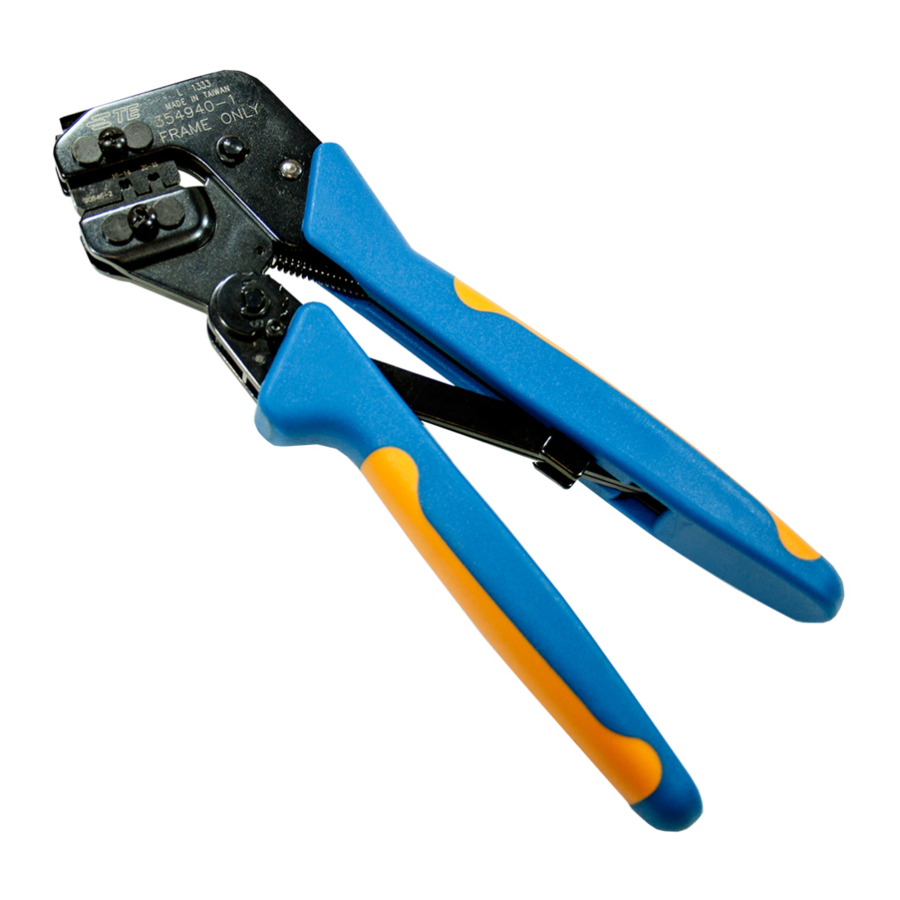
The PRO-CRIMPER III Hand Crimping Tool is a "Commercial" grade tool and is designed
primarily for field installation, repair, maintenance work, or prototyping in industrial,
commercial, or institutional applications. Product crimped with this tool will meet the crimp
height requirement for hand tools in the appropriate Application Specification (114-series),
but may not comply with other feature parameters of the specification.
TE Connectivity offers a variety of tools to satisfy your performance requirements.
For additional information, contact the Tooling Assistance Center at 1-800-722-1111.
DIE
LOCATOR
ASSEMBLY
ASSEMBLY ‡
91387-2
58516-1
‡ Included with die assembly and available separately.
1. INTRODUCTION
PRO-CRIMPER III Hand Tool Assembly 91387-1
consists of PRO-CRIMPER III Hand Tool Frame
354940-1 and Die Assembly 91387-2. The tool
assembly is used to crimp the contacts listed in
Figure 1. For contact part numbers, contact
PRODUCT INFORMATION at the number at the
bottom of this page.
Read these instructions thoroughly before using the
tool assembly.
Dimensions in this instruction sheet are in metric
NOTE
units [with U.S. customary units in brackets].
Figures are not drawn to scale.
i
©2012 Tyco Electronics Corporation, a TE Connectivity Ltd. company
All Rights Reserved
*Trademark
TE Connectivity, TE connectivity (logo), and TE (logo) are trademarks. Other logos, product and/or Company names may be trademarks of their respective owners.
PRO-CRIMPER* III Hand Crimping
Tool Assembly 91387-1
With Die Assembly 91387-2
Wheel
ADDITIONAL
CONTACT
PRODUCT FAMILY
SUPPORT †
679277-1
4.2 mm Contact System
† Included with tool assembly and available separately.
Figure 1
TOOLING ASSISTANCE CENTER 1-800-722-1111
PRODUCT INFORMATION 1-800-522-6752
Pivot Pin
Back of Tool Frame
(Wire Side)
Ratchet
SIZE
INSULATION
(mm [in.])
DIAMETER (mm [in.])
26-22
1.19-1.75 [.047-.069]
For additional information on the hand tool frame, refer
to 408-9930.
Reasons for reissue of this instruction sheet are
provided in Section 9, REVISION SUMMARY.
2. DESCRIPTION
(See Figure 1)
The tool consist of a stationary jaw and handle, a
moving jaw and handle, and an adjustable ratchet that
ensures full crimping. The tool features a ratchet
adjustment wheel for adjusting the crimp height.
The die assembly consists of a wire anvil, insulation
anvil, wire crimper, and insulation crimper. When
closed, the dies form two crimping chambers. Each
die is held in the tool frame by a single screw.
This controlled document is subject to change.
For latest revision and Regional Customer Service,
visit our website at www.te.com
Instruction Sheet
408-8917
16 MAR 12 Rev B
PRO-CRIMPER III Hand Tool
Frame 354940-1 (408-9930)
Stationary Handle
Moving Handle
WIRE
STRIP LENGTH
(mm [in.])
2.79-3.30 [.110-.130]
1 of 5
Advertisement
Table of Contents

Related Manuals for TE Connectivity PRO-CRIMPER III


Summary of Contents for TE Connectivity PRO-CRIMPER III
- Page 1 All Rights Reserved PRODUCT INFORMATION 1-800-522-6752 For latest revision and Regional Customer Service, *Trademark visit our website at www.te.com TE Connectivity, TE connectivity (logo), and TE (logo) are trademarks. Other logos, product and/or Company names may be trademarks of their respective owners.
- Page 2 408-8917 Screw Additional Contact Support Retaining Holes Movable Locator Locknut Wire Crimper Chamfered Die Retaining Short Die Edge (Ref) Retaining Pins Screw Long Die Offset (Ref) Retaining Jaws Screw Wire Insulation Anvil Crimper Insulation Anvil Figure 2 Attached to the outside of the tool frame is a locator 8.
- Page 3 408-8917 5. ADJUSTMENTS 1. Close the tool handles until the ratchet releases, then allow the handles to open FULLY. 5.1. Contact Support Adjustment 2. Holding the contact by the mating end, insert the 1. Make a sample crimp and determine if the contact contact, insulation barrel first, through the front of is straight, bending upward, or bending downward.
- Page 4 408-8917 1. Remove the lockscrew from the ratchet Position Point adjustment wheel. Refer to Figure 4. on Center of (See Table) Wire Barrel 2. Using a screwdriver, adjust the ratchet wheel Opposite Seam from the front of the tool. 3. Observe the ratchet adjustment wheel. If a tighter crimp is required, rotate the adjustment wheel counterclockwise to a higher-numbered setting.
- Page 5 Updated tooling on last page added part number and clarity for additional contact support Tooling Compatible with Die Assembly 91387-2 PRO-CRIMPER III Hand Tool Frame 354940-1 SDE-SA Hand Tool 9-1478240-0 (Instruction Sheet 408-9930) (Instruction Sheet 408-8851) SDE Bench Terminator 1490076-2...
Need help?
Do you have a question about the PRO-CRIMPER III and is the answer not in the manual?
Questions and answers