TE Connectivity PRO-CRIMPER III Assembly Instructions Manual
Hand crimping tool
Hide thumbs
Also See for PRO-CRIMPER III:
- Instruction sheet (11 pages) ,
- Manual (7 pages) ,
- Original instructions manual (6 pages)
Advertisement
Quick Links
Proper use guidelines
Cumulative trauma disorders can result from the prolonged use of manually powered hand tools. Hand tools
are intended for occasional use and low-volume applications. A wide selection of powered application
equipment is available for extended-use production operations. The PRO--CRIMPER III Hand Crimping Tool is
a commercial-grade tool. Product crimped with this tool meets the wire barrel crimp height requirement for hand
tools in the appropriate 114 application specification but might not comply with other feature parameters of the
specification.
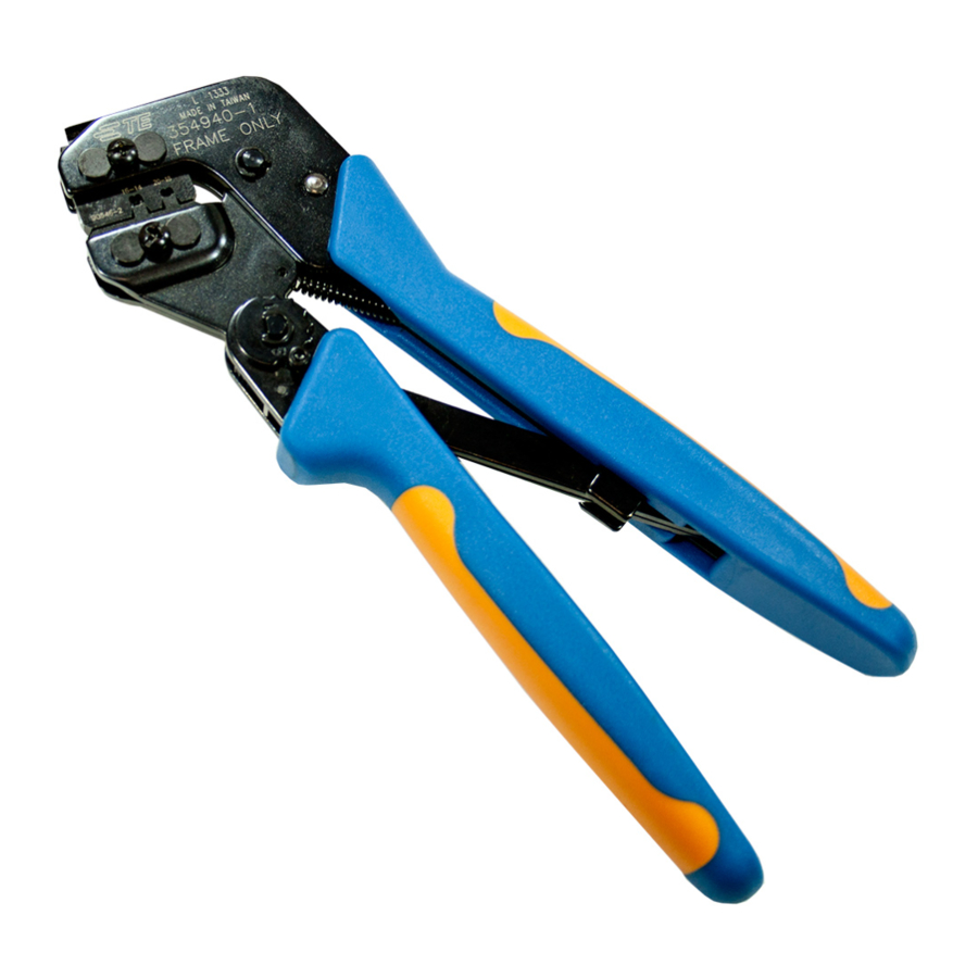
Figure 1: PRO- CRIMPER* III Hand Tool Assembly 58529-1 with Die Assembly 58529-2
Stationary Jaw
1
Back of Tool (Wire Side)
2
Pivot Pin
3
4
PRO-CRIMPER III Hand Crimping Tool Frame 354940-1
5
Stationary Handle
11
Locator Assembly (Supplied with Die Assembly)
© 2024 TE Connectivity Ltd. family of companies.
All Rights Reserved.
TE Connectivity, TE connectivity (logo), and TE (logo) are trademarks. Other logos, product, and/or company names may be trademarks of their respective owners.
PRO- CRIMPER* III Hand Crimping Tool
Assembly 58529-1 with Die Assembly 58529-2
PRODUCT INFORMATION +1 800 522 6752
Moving Handle
6
Ratchet Adjustment Wheel
7
Moving Jaw
8
9
Die Assembly
10
Front of Tool (Locator Side)
This controlled document is subject to change.
For latest revision and Regional Customer Service,
visit our website at www.te.com.
Instruction Sheet
408-9999
2 JUL 2024 Rev D1
1 of 8
Advertisement

Related Manuals for TE Connectivity PRO-CRIMPER III


Summary of Contents for TE Connectivity PRO-CRIMPER III
- Page 1 1 of 8 For latest revision and Regional Customer Service, All Rights Reserved. visit our website at www.te.com. TE Connectivity, TE connectivity (logo), and TE (logo) are trademarks. Other logos, product, and/or company names may be trademarks of their respective owners.
- Page 2 408-9999 Introduction PRO-CRIMPER III Hand Crimping Tool Assembly 58529-1 consists of Die Assembly 58529-2 and PRO- CRIMPER III Hand Tool Frame 354940-1(instruction sheet 408-9930). The die assembly consists of crimping dies and a locator assembly. Reasons for reissue are provided in Section 10, Revision summary.
- Page 3 408-9999 Figure 2: PRO- CRIMPER* III Hand Crimping Tool Assembly Locator Assembly Offset Tool Frame Wire Crimper Die Retaining Pins Chamfer Die Retaining Screws Locator Chamfer Insulation Anvil Insulation Crimper Wire Anvil Installation and removal the die set and locator assembly. (Figure 2) 1.
- Page 4 408-9999 11. Place the nut onto the end of the long screw and tighten the nut enough to hold the locator assembly in place, while still allowing the locator to slide up and down. 12. To disassemble, close the tool handles until the ratchet releases, remove the nut, the locator assembly, the two die retaining screws, and the four die retaining pins, and slide the anvils and crimpers out of the tool jaws.
-
Page 5: Crimping Procedure
408-9999 Crimping procedure NOTE This tool is provided with a crimp adjustment feature. Initially, the crimp height should be verified as specified in Table 2 Refer to Section 6, crimp height inspection, and Section 7, ratchet adjustment, to verify crimp height before using the tool to crimp desired contacts and wire sizes. - Page 6 408-9999 Figure 4: Measuring Crimp Height Dimension “A” Position Point on Center of Wire Barrel Opposite Seam Modified Anvil Table 2: Crimp Size Wire Size AWG Crimp Section (Wire Crimp Height (Max) Size Marking) Dimension A 20-18 1.22 ±.05 [.048 ±.002] 1.41 ±.05 [.056 ±...
-
Page 7: Maintenance And Inspection
408-9999 Figure 5: Ratchet Adjustment Screwdriver Lockscrew (Typ) Ratchet Adjustment Wheel Maintenance and inspection Maintenance Remove dust, moisture, and other contaminants with a clean, soft brush or soft, lint-free cloth. Do not use objects that could damage the dies or tool. ... -
Page 8: Replacement And Repair
408-9999 Replacement and repair If the dies are damaged or worn excessively, they must be replaced. Order replacement dies through your TE representative or go to TE.com and click the Shop TE Store link at the top of the web page. For field service, go to the Service and Repair page on the TE website, or send an e-mail to the address for...
Need help?
Do you have a question about the PRO-CRIMPER III and is the answer not in the manual?
Questions and answers