TE Connectivity PRO-CRIMPER III Instruction Sheet
Hand crimping tool
Hide thumbs
Also See for PRO-CRIMPER III:
- Instruction sheet (11 pages) ,
- Assembly instructions manual (8 pages) ,
- Manual (7 pages)
Advertisement
PROPER USE GUIDELINES
Cumulative Trauma Disorders can result from the prolonged use of manually powered hand tools. Hand tools are intended for occasional use
and low volume applications. A wide selection of powered application equipment for extended-use, production operations is available.
Locator Assembly
(Supplied with Die Assembly)
TE DIE
TE LOCATOR
ASSEMBLY
ASSEMBLY†
90871-2
† Supplied with die assembly. Also available separately.
‡ Contact the Tooling Assistance Center or Product Information (see below) for specific contact part numbers.
1. INTRODUCTION
PRO-CRIMPER III Hand Crimping Tool Assembly
90871-1 consists of Die Assembly 90871-2 and PRO-
CRIMPER III Hand Crimping Tool Frame 354940-1.
The die assembly consists of crimping dies and a
locator assembly.
Read these instructions thoroughly before crimping
any contacts.
Dimensions on this sheet are in millimeters [with
NOTE
inch equivalents provided in brackets]. Figures and
illustrations are for identification only and are not
i
drawn to scale.
Reasons for reissue are provided in Section 11,
REVISION SUMMARY.
© 2011 Tyco Electronics Corporation, a TE Connectivity Ltd. Company
All Rights Reserved
*Trademark
TE Connectivity, TE connectivity (logo), and TE (logo) are trademarks. Other logos, product and/or Company names may be trademarks of their respective owners.
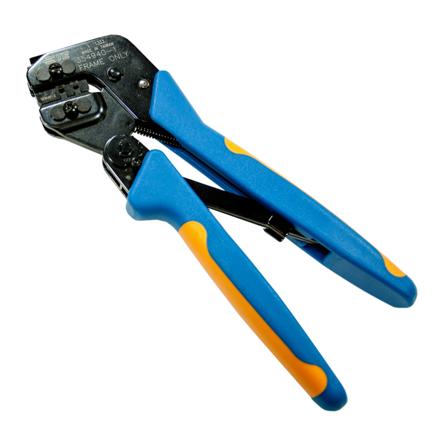
PRO-CRIMPER* III Hand
Crimping Tool Assembly 90871-1
with Die Assembly 90871-1 and -2
Front of Tool
(Locator Side)
Die Assembly
CONTACT
FAMILY‡
.093 Commercial
58516-1
Pin and Socket
TOOLING ASSISTANCE CENTER 1-800-722-1111
PRODUCT INFORMATION 1-800-522-6752
Stationary Jaw
Moving Jaw
Ratchet
Adjustment Wheel
Moving Handle
SIZE (AWG)
20-18
16-14
Figure 1
2. DESCRIPTION
(Figure 1 and Figure 2)
The tool features a tool frame with a stationary jaw
and handle, a moving jaw, a moving handle, and an
adjustable ratchet that ensures full contact crimping.
The tool frame holds a die assembly with two crimping
sections.
The die assembly features a wire anvil, an insulation
anvil, a wire crimper, and an insulation crimper.
Attached to the outside of the frame is a locator
assembly, which contains a locator, a spring retainer,
and a contact support.
This controlled document is subject to change.
For latest revision and Regional Customer Service,
visit our website at www.te.com
Instruction Sheet
408-9966
13 OCT 11 Rev C
Back of Tool
(Wire Side)
Pivot Pin
PRO-CRIMPER III
Hand Crimping Tool
Frame 354940-1
(408-9930)
Stationary
Handle
WIRE
INSUL DIA
STRIP LENGTH
3.96 to 4.72
3.56 [.140] Max
[.156 to .186]
1 of 6
LOC B
Advertisement
Table of Contents

Related Manuals for TE Connectivity PRO-CRIMPER III


Summary of Contents for TE Connectivity PRO-CRIMPER III
- Page 1 PRODUCT INFORMATION 1-800-522-6752 For latest revision and Regional Customer Service, *Trademark visit our website at www.te.com LOC B TE Connectivity, TE connectivity (logo), and TE (logo) are trademarks. Other logos, product and/or Company names may be trademarks of their respective owners.
- Page 2 408-9966 Locator Tool Frame Assembly Locator Die Retaining Pins Chamfer Insulation Crimper Wire Crimper Offset Wire Anvil Die Retaining Insulation Die Retaining Chamfer Screw Anvil Screw Figure 2 Die retaining pins and die retaining screws are used to 8. Carefully close the tool handles, making sure that position and secure the dies in the tool frame.
-
Page 3: Crimping Procedure
408-9966 The ratchet has detents that create audible clicks Adjustment, to verify crimp height before using the NOTE as the tool handles are closed. tool to crimp desired contacts and wire sizes. Refer to the table in Figure 1 and select wire of the specified size and insulation diameter. - Page 4 408-9966 4. Hold the contact in position and squeeze the tool 3. Using a crimp height comparator, measure the handles together until ratchet engages sufficiently to wire barrel crimp height as shown in Figure 4. If the hold the contact in position. Do NOT deform crimp height conforms to that shown in the table, insulation barrel or wire barrel.
-
Page 5: Maintenance
408-9966 8. MAINTENANCE Available separately, PRO-CRIMPER III Hand Crimping Tool Repair Kit 679221-1 includes a Ensure that the tool and dies are clean by wiping them replacement nut and a variety of pins, rings, screws, with a clean, soft cloth. Remove any debris with a and springs. - Page 6 408-9966 Tooling Used With 90871-2 Rev C 6 of 6...
Need help?
Do you have a question about the PRO-CRIMPER III and is the answer not in the manual?
Questions and answers