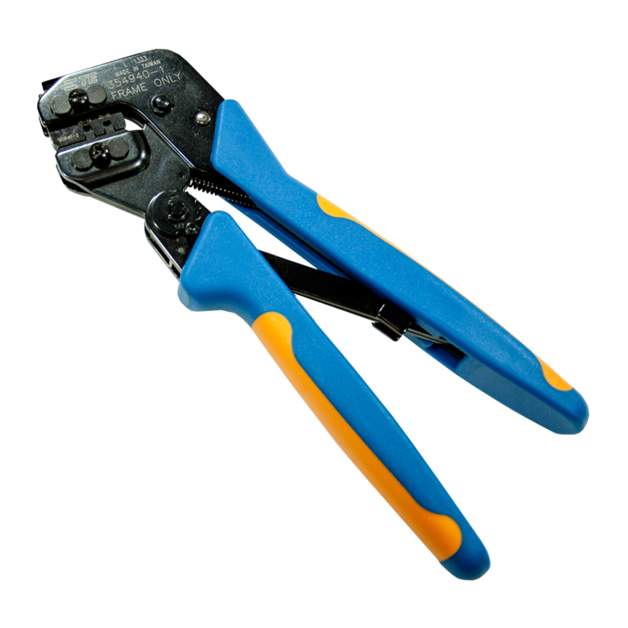
TE Connectivity PRO-CRIMPER III Instruction Sheet
Hand crimping tool assembly and die assemblies
Hide thumbs
Also See for PRO-CRIMPER III:
- Instruction sheet (9 pages) ,
- Assembly instructions manual (8 pages) ,
- Manual (7 pages)
Advertisement
Quick Links
PROPER USE GUIDELINES
Cumulative trauma disorders can result from the prolonged use of manually powered hand tools. Hand tools are intended for occasional
use and low-volume applications. A wide selection of powered application equipment is available for extended-use production operations.
Figure 1: PRO-CRIMPER III Hand Crimping Tool Assembly 58546-1 with Die Assembly 58545-1
1
2
3
4
5
6
The PRO-CRIMPER III Hand Crimping Tool is a commercial-grade tool and is designed primarily for field installation,
repair, maintenance work, or prototyping in industrial, commercial, or institutional applications. Product crimped with
this tool meets the crimp height requirement for hand tools in the appropriate application specification (114-series),
but might not comply with other feature parameters of the specification. TE Connectivity offers a variety of tools to
satisfy your performance requirements. For additional information, contact the Tooling Assistance Center (800-722-
1111).
© 2022 TE Connectivity Ltd. family of companies.
All Rights Reserved.
TE Connectivity, TE connectivity (logo), and TE (logo) are trademarks. Other logos, product, and/or company names may be trademarks of their respective owners.
PRO-CRIMPER™ III
Hand Crimping Tool Assembly 58546-1
and Die Assemblies 58545-[ ]
Die set 58545-1
Crimper (upper die)
Anvil (lower die)
Stationary jaw
Moving jaw
Emergency ratchet release
PRODUCT INFORMATION 1-800-522-6752
7
Ratchet adjustment wheel
8
Ratchet adjustment screw
9
Pivot pin
10
Die-retaining screws (2)
Handle
11
This controlled document is subject to change.
For latest revision and Regional Customer Service,
visit our website at www.te.com.
Instruction Sheet
408-8678
12 JUL 2022 Rev F
1 of 11
Advertisement

Summary of Contents for TE Connectivity PRO-CRIMPER III
- Page 1 1 of 11 For latest revision and Regional Customer Service, All Rights Reserved. visit our website at www.te.com. TE Connectivity, TE connectivity (logo), and TE (logo) are trademarks. Other logos, product, and/or company names may be trademarks of their respective owners.
- Page 2 PRO-CRIMPER III Hand Crimping Tool Assembly 58546-1 for SOLISTRAND™ terminals and splices is the tool and die set shown in Figure 1. The tool consists of the PRO-CRIMPER III Hand Crimping Tool Frame 354940-1 (instruction sheet 408-9930) and the die assemblies listed in Table 1. This tool is used to crimp the terminals listed in Table 1.
- Page 3 408-8678 3. INSTALLING THE DIE ASSEMBLY 1. Open the tool handles and remove the two die-retaining screws from the tool jaws (see Figure 1). 2. Place the upper die in the stationary jaw of the tool frame so that the largest indenter is facing inward. 3.
- Page 4 408-8678 5. Center the terminal or splice wire barrel on the anvil of the upper die as shown in Figure 3, Figure 4, and Figure 5. If the brazed seam on the terminal or splice is visible, orient it toward the indenter. Figure 3: Crimping a splice Figure 4: Crimping a parallel splice Wire barrel centered on anvil of lower die...
- Page 5 408-8678 6. While holding the wire barrel in place, squeeze the tool handles together until the ratchet engages sufficiently to hold the terminal or splice in position. Do not deform the insulation barrel or wire barrel. 7. Insert the stripped wire into the wire barrel, making sure that the insulation does not enter the wire barrel.
- Page 6 408-8678 6. INSPECTING THE CRIMP Inspect crimped terminals and splices by checking the features shown in Figure 6. Poor crimps (Figure 7) can be avoided by carefully following the procedures provided in section 5, and by following the tool maintenance procedures provided in section 9.
- Page 7 7. INSPECTING THE CRIMP HEIGHT This inspection requires the use of plug gages conforming to the dimensions provided in Figure 8 and Table 2. TE Connectivity does not manufacture or market these gages. Figure 8: Recommended plug gage design 4 50.8 [2.00] minimum (typical)
- Page 8 408-8678 4. Align the NO GO element and try to insert it straight into the same crimping chamber. The NO GO element can start entry, but it must not pass completely through the crimping chamber (Figure 10). Figure 10: NO GO element ...
- Page 9 408-8678 8. ADJUSTING THE RATCHET The ratchet is preset prior to shipment, but it is important to verify the crimp height using a micrometer or caliper. Use and wear can cause the tool to go out of adjustment. Inspect the crimp height and adjust the ratchet, if necessary, on a regular basis.
-
Page 10: Maintenance And Inspection
10. REPLACEMENT AND REPAIR Customer-replaceable parts are shown in Figure 1. The PRO-CRIMPER III Hand Crimping Tool Repair Kit 679221-1 (available separately) includes a replacement nut and a variety of pins, rings, screws, and springs. Order the repair kit and replaceable parts through your TE representative. You can also order parts by any of the following methods: ... - Page 11 408-8678 Figure 12: Tools that can use Die Assembly 58545-[ ] Die Assembly 58545-1 for Die Assembly 58545-1 for PRO-CRIMPER III Hand Tool 354940-1 SDE PEW-12 Hand Tool 9-1478240-0 (instruction sheet 408-9930) (instruction sheet 408-8851) Die Assembly 58545-3 for Die Assembly 58545-4 for...


Need help?
Do you have a question about the PRO-CRIMPER III and is the answer not in the manual?
Questions and answers