Table of Contents
Advertisement
Quick Links
EN50155
Wireless
Q
I
uick
nstallation
ACCESS POINT
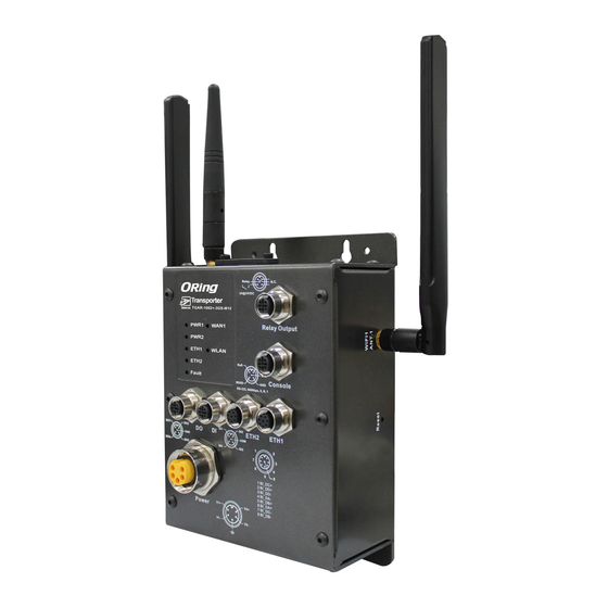
Introduction
The
TGAP-820(+)-M12 series
are reliable WLAN access points with one
802.11 ac/g/n wireless modules alongside two Gigabit LAN ports in M12
connectors. The two Ethernet ports allow you to form Daisy Chain structure to
reduce the use of the ports. The series includes PoE models
M12)
and non-PoE models
(TGAP-820-M12)
and M connectors to ensure tight and robust connections, the devices
guarantee reliable operation against environmental disturbances, such as
vibration and shock, and are ideal for rolling stock applications. The
devices also provide dust-tight connection and reverses SMA-type
connectors for any reverse SMA-type antennas to extend communication
distance. Configurations can be made through the LAN or WLAN interface.
Package Contents
The
TGAP-820(+)-M12
are shipped with the following items. If any of these
items is missing or damaged, please contact your customer service
representative for assistance.
Contents
Pictures
TGAP-820-M12 or
TGAP-820+-M12
CD
2.4GHz/5GHz
Antenna
QIG
Preparation
Before you begin installing the device, make sure you have all of the package
contents available and a PC with Microsoft Internet Explorer 6.0 or later, for
using web-based system management tools.
Safety & Warnings
Elevated Operating Ambient:
If installed in a closed environment, make sure
the operating ambient temperature is compatible with the maximum
ambient temperature (Tma) specified by the manufacturer.
Reduced Air Flow:
Make sure the amount of air flow required for safe operation
of the equipment is not compromised during installation.
Mechanical Loading:
Make sure the mounting of the equipment is not in a
hazardous condition due to uneven mechanical loading.
Circuit Overloading:
Consideration should be given to the connection of the
equipment to the supply circuit and the effect that overloading of the circuits
might have on overcurrent protection and supply wiring. Appropriate
consideration of equipment nameplate ratings should be used when addressing
this concern.
Q I G
TGAP-820(+)-M12
TGAP-820(+)-M12
G
uide
Dimension
(TGAP-820+-
. With EN50155 compliance
125.6
Relay
N.C.
1A@24VDC
TGAP-820+-M12
PWR1
Relay Output
PWR2
(P.O.E)
ETH1
WLAN
ETH2
RxD
TxD
N.C.
Fault
RSVD
GND
Console
RS-232, 115200bps, 8, N, 1
DO1
DO2
DO
DI
DI1
DI2
ETH2
ETH1
(P.O.E)
GND
COM
DO4
DO3
DI4
DI3
1
2
7
3
6
4
5
8
1 BI_DC+
2 BI_DD+
3 BI_DD-
4 BI_DA-
5 BI_DB+
6 BI_DA+
Power
V1+
V2+
7 BI_DC-
8 BI_DB-
V1-
V2-
56.5
86.0
Number
Panel Layouts
X 1
X 1
14
Relay
1A@24VDC
TGAP-820+-M12
1
PWR1
2
PWR2
X 3
(P.O.E)
3
ETH1
WLAN
4
ETH2
RxD
6
5
Fault
RSVD
RS-232, 115200bps, 8, N, 1
11
12
DO1
DO2
DO
DI
DI1
DI2
ETH2
GND
COM
(P.O.E)
X 1
DO4
DO3
DI4
DI3
13
Power
V1+
V2+
V1-
V2-
TGAP-820+-M12
Side View
1907-2-29-TGAP820M12-1.0
15.0
Relay
N.C.
1A@24VDC
TGAP-820-M12
PWR1
Relay Output
PWR2
ETH1
WLAN
ETH2
RxD
TxD
N.C.
Fault
RSVD
GND
Console
RS-232, 115200bps, 8, N, 1
DO1
DO2
DO
DI
DI1
DI2
ETH2
ETH1
GND
COM
DO4
DO3
DI4
DI3
1
2
7
3
6
4
5
8
1 BI_DC+
2 BI_DD+
3 BI_DD-
4 BI_DA-
5 BI_DB+
6 BI_DA+
Power
V1+
V2+
7 BI_DC-
8 BI_DB-
V1-
V2-
R2.5
12.5
R4.0
19.1
65
Front View
1. LED for PWR1 status
2. LED for PWR2 status
N.C.
14
Relay
N.C.
(with PoE indicator)
1A@24VDC
7
7
3. LED for Ethernet port 1
TGAP-820-M12
Relay Output
Relay Output
1
PWR1
status
2
PWR2
3
ETH1
WLAN
8
8
4. LED for Ethernet port 2
TxD
4
ETH2
RxD
TxD
N.C.
6
N.C.
5
Fault
Console
Console
GND
RSVD
GND
status
RS-232, 115200bps, 8, N, 1
9
11
9
5. LED for fault relay
10
12
10
ETH1
DO1
DO2
DO
DI
DI1
DI2
ETH2
ETH1
6. LED for WLAN connection
GND
COM
1
2
DO4
DO3
DI4
DI3
1
2
7
3
7
3
7. Fault relay connector
6
4
6
4
5
13
5
8
8
1 BI_DC+
1 BI_DC+
2 BI_DD+
2 BI_DD+
8. Console port
3 BI_DD-
3 BI_DD-
4 BI_DA-
4 BI_DA-
5 BI_DB+
5 BI_DB+
6 BI_DA+
6 BI_DA+
7 BI_DC-
7 BI_DC-
Power
V1+
V2+
8 BI_DB-
8 BI_DB-
9. Ethernet port 1
V1-
V2-
10. Ethernet port 2(with PoE)
11. Digital output
12. Digital input
13. Power connector
TGAP-820-M12
14. 2.4/5GHz antenna
1. Antenna connector
2. Reset button
1
2
PRINTED ON RECYCLED PAPER
EN50155 Industrial Wireless LAN
Access Point
Installation
Wall-mount
The device can be fixed to the wall. Follow the steps below
to install the device on the wall.
Step 1:
Hold the
d
evice upright against the wall
Step 2:
Insert four screws through the large opening of
the keyhole-shaped apertures at the top and bottom of
the unit and fasten the screw to the wall with a screwdriver.
Step 3:
Slide the
d
evice downwards and tighten the four
screws for added stability.
Wiring
For pin assignments of power, console and relay output ports, please refer to the following tables.
Grounding
Grounding and wire routing help limit the effects of noise due to electromagnetic interference
(EMI). Run the ground connection from the grounding pin on the power connector to the grounding
surface prior to connecting devices.
POWER PORT PINOUTS
The device supports two sets of power supplies and uses the M23 5-pin
female connector on the front panel for the dual power inputs.
Step 1:
Insert a power cable to the power connector on the device.
Step 2:
Rotate the outer ring of the cable connector until a snug fit is
achieved. Make sure the connection is tight.
RELAY OUTPUT PORT AND CONSOLE
DI/DO Port Pinouts
PORT PINOUTS
RxD
TxD
DI1
Relay
N.C.
N.C.
RSVD
GND
DI4
1A@24VDC
RS-232, 115200bps, 8, N, 1
Network Connection
The AP has two 10/100/1000 Base-T(X) Ethernet ports. According to the link type, the AP uses CAT
3, 4, 5, 5e, UTP cables to connect to any other network device (PCs, servers,
routers, or hubs). Please refer to the following table for cable specifications.
Cable
Type
Max. Length
Connector
10Base-T
Cat. 3, 4, 5 100-ohm
UTP 100 m (328 ft)
M12
100Base-T(X) Cat. 5 100-ohm UTP
UTP 100 m (328 ft)
M12
1000Base-T
Cat. 5/Cat. 5e 100-ohm UTP UTP 100 m (328 ft)
M12
M12/8P Pin Definition
PIN
Definition
1
2
1
BI_DC+
7
3
6
4
2
BI_DD+
5
8
3
BI_DD-
4
BI_DA-
5
BI_DB+
6
BI_DA+
7
BI_DC-
8
BI_DB-
Quick Installation Guide
Version 1.0
V1+
V2+
V1-
V2-
DI
DO
DI2
DO1
DO2
COM
GND
DI3
DO4
DO3
d
evicees,
Advertisement
Table of Contents

Related Manuals for ORiNG TGAP-820-M12


Summary of Contents for ORiNG TGAP-820-M12
- Page 1 Insert a power cable to the power connector on the device. Step 2: Rotate the outer ring of the cable connector until a snug fit is Front View TGAP-820-M12 or achieved. Make sure the connection is tight. TGAP-820+-M12 RELAY OUTPUT PORT AND CONSOLE...
- Page 2 For information on operating the device Wireless Security SSID broadcast disable using ORing’s Open-Vision management utility, please go to ORing website. Protocol Support Protocol ARP,BOOTP, DHCP, DNS, HTTPs, IP, ICMP, SNTP, TCP, UDP, RADIUS, SNMP, STP, RSTP...
Need help?
Do you have a question about the TGAP-820-M12 and is the answer not in the manual?
Questions and answers