Advertisement
Quick Links
DO
GUIDE
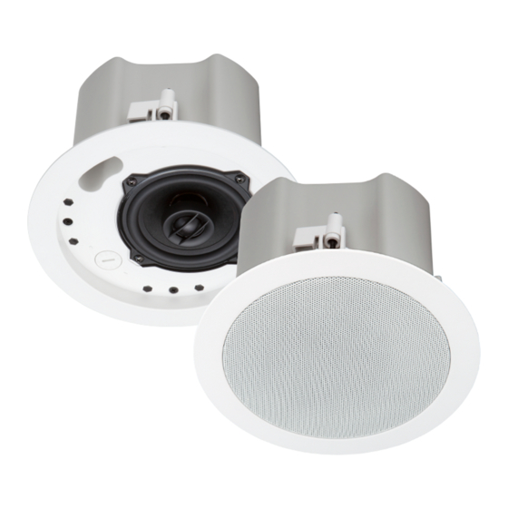
SAROS ICI4T/SAROS ICI6T
Saros
Integrator 2-Way In-Ceiling Speakers
®
The Saros
®
Integrator series of 2-way, in-ceiling speakers deliver easy installation and excellent performance in 4- and 6-inch sizes for cost-sensitive
commercial applications.
Aside from physical dimensions, the ICI4T and ICI6T speakers install in an identical manner. For simplicity within this guide, the term "speaker" is used except
where noted.
DO
Install the Speaker
Prepare the Mounting Hole
Before finalizing the speaker location, check to make sure there are no fixtures, pipes, air ducts, joists, or other possible obstructions. If applicable, use a
good quality stud finder to locate joists. If there are no obstructions, use the supplied template to trace an outline of the mounting hole.
For drop tile ceilings, remove the ceiling tile and place on a flat surface to trace the mounting hole. For drywall or standard construction ceilings, use the
template to trace the mounting hole directly on the ceiling.
Install the Speaker Cable
Run the speaker cable from the audio source to the speaker location, observing all appropriate local codes. Strip the ends of the speaker cable's wires
approximately 1/8" to 3/16" (~3 mm to ~5 mm), and twist the strands.
NOTE:
Install in accordance with all local and national electrical codes.
Install the Tile Bridge (Drop Tile Ceiling Installations Only)
The included tile bridge components provide proper support when the speaker is installed in a typical drop tile ceiling, as shown in the following diagram.
1.
Based on the location of the mounting hole determined in "Prepare the Mounting Hole" above, use the two supplied screws to attach the support
ring to the rails so that when installed, the ring is aligned with the mounting hole and the rails rest on the ceiling grid frame.
2.
The support ring position on the rails is adjustable to enable off-center speaker positioning. The tile bridge assembly can be maneuvered to fit
through the speaker cutout in blind-mount situations.
Tile Bridge Assembly
Insert screws
(supplied)
22.06 in
22.06 in
25 3/4 in
25 3/4 in
(560 mm)
(560 mm)
(655 mm)
(655 mm)
DO
Check the Box
QUANTITY
1
Rails, Mounting
Items for SAROS ICI4T
1
Template, Cutout
1
Grille
1
C-Ring, Mounting
Items for SAROS ICI6T
1
Template, Cutout
1
Grille
1
C-Ring, Mounting
Mount or Remove the Speaker
Remove the connector from the speaker and terminate the wires, using the terminals as shown in the following diagram: red to + and
1.
black to –. Use the second terminal pair + and – (not terminated in the diagram) as a pass-thru connection (parallel) to additional speakers.
Cable clamp screw
Cable clamp plate
Cable clamp screw
Cable clamp plate
Safety tether rigging point
2.
Route the connector and speaker cable between the cable clamp plates and attach the connector to the speaker.
3.
Tighten the two cable clamp screws to engage the cable clamp plates and secure the conduit (if used) and speaker cable(s). Do not overtighten.
4.
Attach the SPKA-ST-15 Safety Tether/Tie Down Kit (sold separately) to the rigging point on the rear of the speaker enclosure, and secure it to
the structure as may be required by local building codes.
5.
Insert and secure the speaker into the ceiling. The speaker has four toggle clamps that simplify the mounting process. The toggle clamps offer
two positions to accommodate both standard and extra thick surfaces up to 2.4 inches (61 mm). For extra thick tiles, reset the toggle clamps to
the upper position before continuing.
a.
With the toggle clamps turned inward, insert the speaker into the opening.
b.
Hold the speaker against the ceiling and begin tightening the four screws (shown in the following diagram) on the front of the speaker. The
toggle clamps first rotate into clamping position (as indicated in the illustration below) and then begin holding the speaker to the ceiling.
Clamp screw
Clamp screw
Clamp screw
Clamp screw
c.
Tighten the screws until the speaker is secure. Do not overtighten.
Remove the speaker by performing step 5 in reverse.
ITEM
PART NUMBER
Speaker wire
2046653
2046997
2047257
2047136
2046996
2047256
2047137
Advertisement

Subscribe to Our Youtube Channel
Related Manuals for Crestron SAROS ICI4T


Summary of Contents for Crestron SAROS ICI4T
- Page 1 QUANTITY ITEM PART NUMBER SAROS ICI4T/SAROS ICI6T Rails, Mounting 2046653 Saros Integrator 2-Way In-Ceiling Speakers Items for SAROS ICI4T ® Template, Cutout 2046997 Grille 2047257 The Saros ® Integrator series of 2-way, in-ceiling speakers deliver easy installation and excellent performance in 4- and 6-inch sizes for cost-sensitive...
- Page 2 (1) This device may not cause harmful interference, and (2) this device must accept any interference received, including interference that may cause undesired operation. Crestron product development software is licensed to Crestron dealers and Crestron Service Providers (CSPs) under a limited non-exclusive, non-transferable Software Development Tools License Agreement. Crestron product operating system software is licensed to Crestron dealers, CSPs, and CAUTION: Changes or modifications not expressly approved by the manufacturer responsible for compliance could void the user’s authority to operate the equipment.
Need help?
Do you have a question about the SAROS ICI4T and is the answer not in the manual?
Questions and answers