
Related Manuals for Crestron SAROS IC6VLPT-W-T-EACH+


Summary of Contents for Crestron SAROS IC6VLPT-W-T-EACH+
- Page 1 SAROS® IC6VLPT-W-T-EACH+ and SAROS® IC6ULPT-W-T-EACH+ Product Manual Crestron Electronics, Inc.
- Page 2 Inc. in the United States and/or other countries. Other trademarks, registered trademarks, and trade names may be used in this document to refer to either the entities claiming the marks and names or their products. Crestron disclaims any proprietary interest in the marks and names of others. Crestron is not responsible for errors in typography or photography.
-
Page 3: Table Of Contents
Install the Speaker Cable Install the Tile Bridge Paint the Speaker Grille Connect the Speaker Cable Mount the Speaker Set the Transformer Tap Selector Attach the Speaker Grille Resources Crestron Support and Training Product Certificates Product Manual — Doc. 9398A Contents • iii... -
Page 4: Overview
70V and 100V distributed speaker systems. Saros® speakers by Crestron deliver professional grade performance and flexible installation in a range of popular sizes for demanding commercial applications. Solid construction, easy installation, and high-end components are hallmarks of the Saros speaker line. Ideal for use in... -
Page 5: Saros Ic6Ulpt-W-T-Each
SAROS IC6ULPT-W-T-EACH+ The SAROS IC6ULPT-W-T-EACH+ is designed for quick and easy installation and years of reliable performance. Its zero-bezel frameless grille achieves an unobtrusive and contemporary appearance well-suited for use in restaurants, retail spaces, houses of worship, universities, and office buildings. Installing the grille requires no hardware or tools, utilizing powerful magnets to hold it in place. -
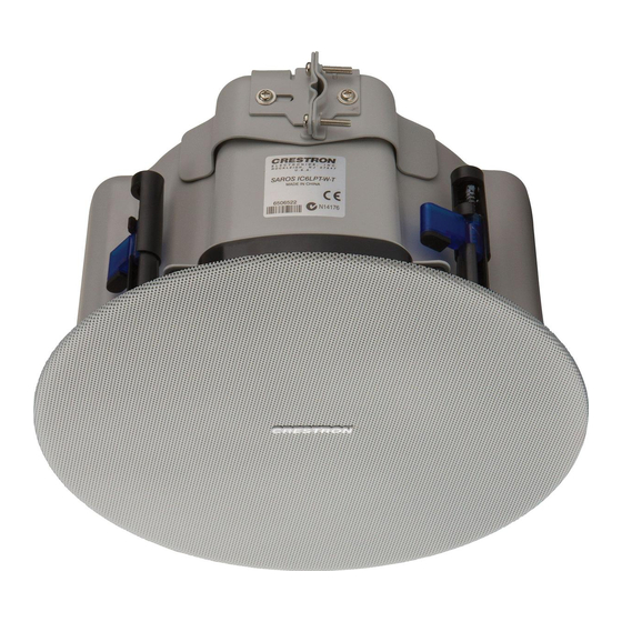
Page 6: Saros Ic6Vlpt-W-T-Each
SAROS IC6VLPT-W-T-EACH+ The SAROS IC6VLPT-W-T-EACH+ is designed for quick and easy installation and years of reliable performance. Its zero-bezel frameless grille achieves an unobtrusive and contemporary appearance well-suited for use in restaurants, retail spaces, houses of worship, universities, and office buildings. Installing the grille requires no hardware or tools, utilizing powerful magnets to hold it in place. -
Page 7: Specifications
Specifications This section provides the following information: • SAROS IC6ULPT-W-T Specifications • SAROS IC6VLPT-W-T Specifications SAROS IC6ULPT-W-T Specifications Product specifications for the SAROS IC6ULPT-W-T. Product Specifications Features and Performance Woofer 4 in. (102 mm) polypropylene with ring mode decoupled cloth surround and steel basket Tweeter 0.98 in. (25 mm) titanium dome Crossover Point 2.5 kHz Impedance... -
Page 8: Dimension Drawings
Dimensions Diameter 10.63 in. (270 mm) not including mounting dogs Depth 2.43 in. (62 mm) Weight 4.5 lb (2.04 kg) Compliance Regulatory Model: M202302001 To search for product certificates, refer to support.crestron.com/app/certificates. Dimension Drawings 8 • SAROS® IC6VLPT-W-T-EACH+ and SAROS® IC6ULPT-W-T-EACH+ Product Manual — Doc. 9398A... -
Page 9: Saros Ic6Vlpt-W-T Specifications
SAROS IC6VLPT-W-T Specifications Product specifications for the SAROS IC6VLPT-W-T. Product Specifications Features and Performance Woofer 6.5 in. (165 mm) polypropylene with ring mode decoupled cloth surround and steel basket Tweeter 0.98 in. (25 mm) titanium dome, horn loaded Crossover Point 2.5 kHz Impedance 8 Ω nominal with transformer set to 8 Ω Transformer Taps 3.75 W, 7.5 W, 15 W, 30 W, 60 W at 70V;... - Page 10 (SPKA-ST-15 sold separately) Dimensions Diameter 10.63 in. (270 mm) not including mounting dogs Depth 4.05 in. (103 mm) Weight 8.3 lb (3.76 kg) Compliance Regulatory Model: M202302001 To search for product certificates, refer to support.crestron.com/app/certificates. 10 • SAROS® IC6VLPT-W-T-EACH+ and SAROS® IC6ULPT-W-T-EACH+ Product Manual — Doc. 9398A...
-
Page 11: Dimension Drawings
Dimension Drawings Product Manual — Doc. 9398A SAROS® IC6VLPT-W-T-EACH+ and SAROS® IC6ULPT-W-T-EACH+ • 11... -
Page 12: Installation
Installation Refer to the following sections for instructions on how to install the Saros in-ceiling low profile speakers. SAROS IC6ULPT-W-T-EACH+ Installation on page 12 SAROS IC6VLPT-W-T-EACH+ Installation on page 19 SAROS IC6ULPT-W-T-EACH+ Installation Refer to the following sections to install the SAROS IC6ULPT-W-T-EACH+. In the Box Qty. -
Page 13: Prepare The Mounting Hole
Prepare the Mounting Hole Before finalizing the speaker location, check to make sure there are no fixtures, pipes, air ducts, joists, or other possible obstructions. If applicable, use a good quality stud finder to locate joists. If there are no obstructions, use the supplied template to trace an outline of the mounting hole on the ceiling surface. -
Page 14: Paint The Speaker Grille
To assemble and install the tile bridge: 1. Based on the location of the mounting hole determined in the Prepare the Mounting Hole steps, use the supplied self tapping screws to attach the support ring to the rails so that when installed, the ring is aligned with the mounting hole and the rails rest on the ceiling grid frame. -
Page 15: Connect The Speaker Cable
Connect the Speaker Cable Connect the speaker cable to the input of the speaker before mounting it into the ceiling: 1. Strip approximately 1/8 in. to 3/16 in. (3 mm to 5 mm) of insulation from the ends of the leads of the included speaker cable pigtail, then twist the strands. 2. - Page 16 4. Hold the speaker in place, and with a Philips head screwdriver, rotate each toggle clamp screw on the baffle side of the speaker clockwise to rotate the toggle clamps so they clamp onto the ceiling surface. 5. Tighten the toggle clamp screws until the speaker is secure. Do not overtighten the screws. 16 •...
-
Page 17: Set The Transformer Tap Selector
Set the Transformer Tap Selector The speaker features a 70/100V transformer tap selector switch on the baffle side. The tap selector is used to either set the speaker for 8 Ω operation or select a power level for the speaker when adding it to a 70V or 100V distributed audio system. To adjust the switch: 1. - Page 18 over the baffle, thread the included safety tether through one of the holes in the grille along the edge and press the tether into the safety tether anchor point on the baffle of the speaker. 18 • SAROS® IC6VLPT-W-T-EACH+ and SAROS® IC6ULPT-W-T-EACH+ Product Manual —...
-
Page 19: Saros Ic6Vlpt-W-T-Each+ Installation
SAROS IC6VLPT-W-T-EACH+ Installation Refer to the following sections to install the SAROS IC6VLPT-W-T-EACH+. In the Box Qty. Description SAROS IC6ULPT-W-T-EACH+ Additional Items Wire Nut (2061488) Tile Bridge Rail (2061676) Accessory Bag (2062047) Mesh Grille (2062049) C-Ring (2062051) Cutout Template (2062048) Transformer Tap Cover (2062361) Self Tapping Screw, 5 mm, Flathead (2062363) Prepare the Mounting Hole Before finalizing the speaker location, check to make sure there are no fixtures, pipes, air ducts,... -
Page 20: Install The Speaker Cable
2. For a finished drywall ceiling, use a drywall saw to cut a small hole at a 45° angle. An angled cut simplifies repair since the removed piece can be reinserted to help plug the hole. Use a piece of stiff wire, bent into an L shape, with one end long enough to explore an area equal to the size of the speaker. -
Page 21: Paint The Speaker Grille
To assemble and install the tile bridge: 1. Based on the location of the mounting hole determined in the Prepare the Mounting Hole steps, use the supplied self tapping screws to attach the support ring to the rails so that when installed, the ring is aligned with the mounting hole and the rails rest on the ceiling grid frame. -
Page 22: Connect The Speaker Cable
Connect the Speaker Cable Connect the speaker cable to the input of the speaker before mounting it into the ceiling: 1. Remove the screws securing the rear cover panel, and remove the cover panel to expose the terminal block. 2. Route the speaker cable through the cover cable clamp, then tighten the cable cover clamp. -
Page 23: Mount The Speaker
Mount the Speaker Follow the steps below to mount the speaker into the ceiling: 1. If the install requires that the speaker be secured to building architecture, attach a SPKA- ST-15 safety tether (not included) to the speaker housing and an architectural anchor point. - Page 24 2. Adjust the depth of the toggle clamps. The toggle clamps on the SAROS IC6VLPT-W-T-EACH+ can accommodate surface thicknesses up to 2.4 in. (64 mm). 3. With the toggle clamps turned fully inwards, push the speaker housing through the mounting hole. 4. Hold the speaker in place, and with a Philips head screwdriver, rotate each toggle clamp screw on the baffle side of the speaker clockwise to rotate the toggle clamps so they clamp onto the ceiling surface.
- Page 25 Product Manual — Doc. 9398A SAROS® IC6VLPT-W-T-EACH+ and SAROS® IC6ULPT-W-T-EACH+ • 25...
-
Page 26: Set The Transformer Tap Selector
5. Tighten the toggle clamp screws until the speaker is secure. Do not overtighten the screws. Set the Transformer Tap Selector The speaker features a 70/100V transformer tap selector switch on the baffle side under a cap. The tap selector is used to either set the speaker for 8 Ω operation or select a power level for the speaker when adding it to a 70V or 100V distributed audio system. -
Page 27: Attach The Speaker Grille
Attach the Speaker Grille Attach the included grille to the speaker by placing it over the baffle. The magnets on the baffle will attract the grille and hold it in place. For an even more secure hold, before placing the grille over the baffle, thread the included safety tether through one of the holes in the grille along the edge and press the tether into the safety tether anchor point on the baffle of the speaker. -
Page 28: Resources
Resources The following resources are provided for the SAROS® IC6VLPT-W-T-EACH+ and SAROS® IC6ULPT-W-T-EACH+. NOTE: You may need to provide your Crestron.com web account credentials when prompted to access some of the following resources. Crestron Support and Training Crestron True Blue Support Crestron Resource Library... - Page 29 Crestron Electronics, Inc. Product Manual — Doc. 9398A 15 Volvo Drive, Rockleigh, NJ 07647 02/23/24 Tel: 888.CRESTRON Specifications subject to Fax: 201.767.7656 change without notice. www.crestron.com...
Need help?
Do you have a question about the SAROS IC6VLPT-W-T-EACH+ and is the answer not in the manual?
Questions and answers