Advertisement
Quick Links
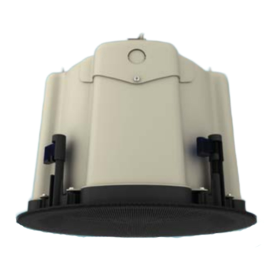
SAROS_ICS8T
Saros
®
speakers by Crestron
®
deliver professional grade performance
and flexible installation in a range of popular sizes for demanding
commercial applications. Solid construction, easy installation, and
high end components are hallmarks of the complete Saros speaker
line.
Ideal for use in background or foreground music, paging, and sound
reinforcement systems, Saros speakers are engineered to achieve
smooth, even coverage, high output, and clear, natural sound quality.
The SAROS_ICS8T model is an 8 inch in-ceiling subwoofer designed
to extend the low frequency response of Crestron's full range Saros
speakers. It is intended for use with Crestron's AMP-series
Commercial Power Amplifiers which can provide low impedance or
70/100 V distributed power to the Saros speaker line. Because of the
internal crossover, no biamping is required.
SAROS_ICS8T subwoofers are available in white or black and may
be painted to blend with the ceiling surface.
1
Installation
Prepare Mounting Hole
Before finalizing the speaker location, check to make sure there are no fixtures, pipes, air ducts, joists,
or other possible obstructions. If applicable, use a good quality stud finder to locate joists. If there are
no obstructions, use the supplied template to trace an outline of the mounting hole.
For drop tile ceilings, remove the ceiling tile and place on a flat surface to trace the mounting hole. For
drywall or standard construction ceilings, use the template to trace the mounting hole directly on the
ceiling.
Install Cable
Run the cable from the audio source to the speaker location, observing all appropriate local codes.
Strip the ends of the speaker cables approximately 1/8" to 3/16" (~3 mm to ~5 mm) and, if the cable is
.
stranded, twist the strands
Install Tile Bridge
The included tile bridge components provide proper support when the speaker is installed in a typical
drop tile ceiling. Refer to the illustration below.
1.
Based on the location of the mounting hole determined in "Prepare Mounting Hole" above, use the
two supplied screws to attach the support ring to the rails so that when installed, the ring is
aligned with the mounting hole and the rails rest on the ceiling grid frame.
2.
Adjust the support ring position as necessary to enable off-center speaker positioning. The tile
bridge assembly can be folded to fit through the speaker cutout in blind-mount situations.
Tile Bridge Assembly
Screws
(Supplied)
Support
Ring
1
QUICKSTART DOC. 7494A (2037421)
®
Saros
8" Subwoofer In-Ceiling Speakers
25.92 in
(659 mm)
www.crestron.com
Specifications subject to
11.13
change without notice.
Install/Remove Grille
The zero-bezel frameless grille is held in place by powerful magnets. A safety tether is included to
prevent any possibility of the grille falling from the ceiling. With the tether attached, place the grille in
position on the speaker. To remove the grille, grip the edges and pull away from the speaker.
Paint the Speaker Grille
Speaker grille painting should be done prior to mounting.
1.
Carefully remove the material on the underside of the grille and set it aside for reinstallation. It
may be necessary to use a knife or other sharp instrument to free an edge of the material so it
can be peeled away. Use care to avoid cutting or tearing the material.
2.
Dry brush or lightly spray the surface to be painted. Use care to avoid clogging the holes in the
grille.
Mount/Remove Speaker
The in-ceiling speaker includes four toggle clamps that simplify the mounting process. If the grille is
mounted on the speaker, remove it before proceeding. (Refer to "Install/Remove Grille" above.)
1.
Referring to the illustrations to the right, remove the screw securing the rear cover panel, and lift
the cover panel off to expose the supplied terminal block.
2.
Route the speaker cable through the cover cable clamp and connect the wires to the terminal
block, using the outer IN terminals: red to + and black to –. Use the inner + and – THRU terminals
to connect a pass-through (parallel) speaker.
3.
Allow some slack in the speaker cable(s) and position the cover panel on the back, making certain
it engages the mounting clips. Secure the cover panel using the screw removed in step 1 and
tighten the cable clamp to secure the cable(s). Do not overtighten. Use a safety tether attached to
the rear enclosure to prevent the speaker from accidentally falling.
4.
The toggle clamps offer two positions to accommodate both standard and extra thick surfaces up
to 2.4 inches (61 mm). For extra thick tiles, reset the toggle clamps to the upper position before
continuing.
a.
With the toggle clamps turned inward, insert the speaker into the opening.
b.
Hold the speaker against the ceiling and begin tightening the four screws on the front of the
speaker. The toggle clamps first rotate into clamping position (as indicated in the front view
illustration to the right) and then begin holding the speaker to the ceiling.
c.
Tighten the screws until the speaker is secure. Do not overtighten.
5.
Speaker removal is accomplished by reversing steps 1 through 4 above.
Set the Transformer Tap Selector Switch
The speakers are equipped with a 70/100 V matching transformer for distributed audio
systems. The transformer tap selector switch on the front panel is used to set the speaker
power level. Use a flat blade screwdriver to adjust the switch.
1.
For SAROS_ICS8T 70 V systems, use the left side settings and select from 3.75, 7.5,
15, 30, or 60 watts.
2.
For SAROS_ICS8T 100 V systems, use the right side settings and select from 7.5,
15, 30, or 60 watts. The X position should not be used.
The switch may also be set to 8Ω operation, bypassing the transformer completely. This
setting should be used only for 8 Ω audio systems.
888.273.7876
201.767.3400
Speaker Cable Connections
Rear
Cover
Screw
Panel
IN
THRU
Cable
Clamp
Speaker
Cable
Terminal Block
Terminal
Not Shown
Block
Mounting
Clips
Safety Tether
Rigging Points
Front View (Grille Removed)
Tighten
Screws
70V
100V
70V
100V
Advertisement

Related Manuals for Crestron SAROS ICS8T


Summary of Contents for Crestron SAROS ICS8T
- Page 1 Panel to extend the low frequency response of Crestron’s full range Saros can be peeled away. Use care to avoid cutting or tearing the material.
- Page 2 Minimum the marks and names or their products. Crestron disclaims any proprietary interest in the marks Mounting Depth and names of others. Crestron is not responsible for errors in typography or photography.
Need help?
Do you have a question about the SAROS ICS8T and is the answer not in the manual?
Questions and answers