
Related Manuals for Crestron SAROS DM-NAX-IC4A-W


Summary of Contents for Crestron SAROS DM-NAX-IC4A-W
- Page 1 View this document in HTML crestron.com/docs/9466 Product Manual SAROS DM-NAX-IC4A-W and SAROS IC4P-W Saros® 3 in. Full-Range In-Ceiling Speaker, White, Textured Crestron Electronics, Inc.
- Page 2 Certain Crestron products contain open source software. For specific information, please visit www.crestron.com/opensource. Crestron, the Crestron logo, DM NAX, DM NVX, and Saros are either trademarks or registered trademarks of Crestron Electronics, Inc. in the United States and/or other countries. Dante is either a trademark or registered trademark of Audinate Pty Ltd. in the United States and/or other countries.
-
Page 3: Table Of Contents
SAROS DM-NAX-IC4A-W Specifications Product Specifications Dimension Drawings SAROS IC4P-W Specifications Product Specifications Dimension Drawings Installation SAROS DM-NAX-IC4A-W Installation In the Box Prepare the Mounting Hole Install the Tile Bridge Install the Ethernet Cable Connect the Ethernet Cable Connect the Output Category Cables (Optional) - Page 4 Residential Mode Security Current User Users Groups 802.1x Configuration To Configure 802.1X Authentication Access the Web Interface with the Crestron Toolbox Application Resources Crestron Support and Training Programmer and Developer Resources Product Certificates iv • Contents Product Manual — Doc. 9466A...
-
Page 5: Overview
SAROS DM-NAX-IC4A-W supports PoE+, DM NAX® Audio-over-IP, and AES67, and powers up to three SAROS IC4P-W passive speakers to act as the hub of a four-speaker system. This section provides the following information: • SAROS DM-NAX-IC4A-W • SAROS IC4P-W SAROS DM-NAX-IC4A-W Audio-over-IP (AoIP) in-ceiling speaker Connects directly to a managed network to route to or from DM NAX®... -
Page 6: Digital Signal Processing
Includes tile bridge for installation in a drop-tile ceiling 80 Hz to 24 kHz frequency response 170° coverage for speech content, 140° coverage for music Audio-over-IP The SAROS DM-NAX-IC4A-W receives up to four channels of DM NAX audio-over-IP or AES67 encoded audio over a standard IP network. DM NAX devices can also receive the audio stream from DM NVX A/V-over-IP devices, and are interoperable with Dante audio devices via the AES67 compatibility mode enabled through Dante Controller®... - Page 7 SAROS IC4P-W Balanced Mode Radiator (BMR) transducer offers enhanced clarity and wider dispersion than a typical conical driver Clean, contemporary grille design Two-step toggle clamps for quick and easy installation Includes tile bridge for installation in a drop-tile ceiling 90 Hz to 30 kHz frequency response 170°...
- Page 8 Plenum Rated The speaker is housed in an integral metal back can, which meets the requirements of UL® 2043 for installation in a plenum space. The wiring connections are accessible behind a rear cover panel. Two mutually exclusive inputs are available, an RJ-45 connector to receive signal from the outputs of a SAROS DM-NAX-IC4A-W (sold separately) and a two pin terminal block connector to receive signal from an external audio amplifier.
-
Page 9: Specifications
Specifications Refer to the following sections for more information on the specifications of the individual Saros® 3 in. in-ceiling speaker models. This section provides the following information: • SAROS DM-NAX-IC4A-W Specifications • SAROS IC4P-W Specifications SAROS DM-NAX-IC4A-W Specifications Product specifications for the SAROS DM-NAX-IC4A-W are provided below. Product Specifications Features &... - Page 10 Controls and Indicators Ethernet (2) Bi-color green/amber LEDs; Left LED indicates Ethernet link status; RIght LED indicates Ethernet activity Power (1) Bi-color white/red LED behavior determined via web UI configuration; White indicates that the device is powered on with audio passing or that signal is present;...
- Page 11 Compliance Regulatory Model: M202010001 FCC Part 15 Class B, IC Class B, CE, UL® 2043 To search for product certificates, refer to support.crestron.com/app/certificates. Product Manual — Doc. 9466A SAROS DM-NAX-IC4A-W and SAROS IC4P-W • 11...
-
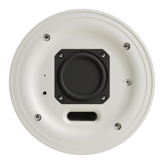
Page 12: Dimension Drawings
Dimension Drawings 12 • SAROS DM-NAX-IC4A-W and SAROS IC4P-W Product Manual — Doc. 9466A... -
Page 13: Saros Ic4P-W Specifications
SAROS IC4P-W Specifications Product specifications for the SAROS IC4P-W are provided below. Product Specifications Features & Performance Transducer 2.83 in. (72 mm) Balanced Mode Radiator (BMR) Frequency Response 90 Hz to 30 kHz (±3 dB) Sensitivity 86 dB @ 1 W/1 m Maximum SPL Coverage 170° conical (speech, up to 4 kHz); 140°... - Page 14 4.28 in. (109 mm) mounting depth; 4.50 in. (115 mm) including grille Weight 2.35 lb (1.06 kg) Compliance Regulatory Model: M202010001 FCC Part 15 Class B, IC Class B, CE, UL® 2043 To search for product certificates, refer to support.crestron.com/app/certificates. 14 • SAROS DM-NAX-IC4A-W and SAROS IC4P-W Product Manual — Doc. 9466A...
-
Page 15: Dimension Drawings
Dimension Drawings Product Manual — Doc. 9466A SAROS DM-NAX-IC4A-W and SAROS IC4P-W • 15... -
Page 16: Installation
Installation Refer to the following sections for instructions on how to install Saros® 3 in. in-ceiling speakers. This section provides the following information: • SAROS DM-NAX-IC4A-W Installation • SAROS IC4P-W Installation SAROS DM-NAX-IC4A-W Installation Refer to the following sections to install the SAROS DM-NAX-IC4A-W. -
Page 17: Install The Tile Bridge
If there are no obstructions, use the supplied template to trace an outline of the mounting hole on the ceiling. Cut the final mounting hole at a 90° angle to the ceiling. For drop tile ceilings, remove the ceiling tile and place on a flat surface to trace the mounting hole. For drywall or standard construction ceilings, use the template to trace the mounting hole directly on the ceiling. -
Page 18: Install The Ethernet Cable
Install the Ethernet Cable Run an Ethernet cable (not included) from a managed POE+ compliant network switch to the speaker location, observing all appropriate local codes. Connect the Ethernet Cable Connect the Network/POE+ port to a managed network switch to apply power and configure the device. -
Page 19: Connect The Output Category Cables (Optional)
Connect the Output Category Cables (Optional) CAUTION: The RJ-45 OUTPUT ports of the SAROS DM-NAX-IC4A-W should only be connected to the RJ-45 INPUT ports of SAROS IC4P-W speakers. These connectors carry up to approximately 10 W speaker-level analog audio signals and can cause equipment damage if connected to other devices. -
Page 20: Mount The Speaker
Mount the Speaker The speaker includes four toggle clamps to secure the speaker in place in the mounting hole. If the grille is mounted on the speaker, remove it before proceeding. 1. With the toggle clamps turned inward, insert the speaker into the mounting hole. 2. -
Page 21: Saros Ic4P-W Installation
SAROS IC4P-W Installation Refer to the following sections to install the SAROS IC4P-W. In the Box Qty. Description SAROS IC4P-W Additional Items Speaker grille (4532326) Rear metal input cap (4535516) Front metal input cap (4535515) Tile bridge ring (4532948) Tile bridge frame, outer (2057231) Tile bridge frame, inner (2057230) Screw, 04-20, 5/16 in., Philips (2007135) Screw, 3 x 6 mm, steel, Philips (2013272) -
Page 22: Install The Tile Bridge
Install the Tile Bridge The included tile bridge components provide proper support when the speaker is installed in a typical drop tile ceiling. Refer to the illustration below. 1. Insert the inner tile bridge rails (with adjustment holes) into their respective outer tile bridge rails. 2. -
Page 23: Connect The Category Cable
that the connecting cable uses straight-through wiring, perform a pin-out continuity test before connecting the speakers and connect PoE last. Some signal level loss should be expected depending on the length of the cable run and the wire gauge of the cable. The following chart provides measured signal losses for different wire gauges at different lengths: Expected Signal Loss at Different Cable Lengths Wire Gauge... -
Page 24: Install The Speaker Cable
Install the Speaker Cable If the audio source for the SAROS IC4P-W is an external amplifier, run the speaker cable (not included) from the audio source to the speaker location, observing all appropriate local codes. Strip the ends of the speaker cable approximately 0.25 in. to 0.50 in. (~6 mm to ~12 mm) and twist the strands. Connect the Speaker Cable CAUTION: Do not connect both the 2-pin terminal block input and RJ-45 input simultaneously. -
Page 25: Mount The Speaker
4. Replace the metal end cap and the screws removed in step 1. NOTE: If installing the speaker without the metal end caps, the screws removed in step 1 should still be screwed back into the speaker back can for the best acoustic performance. Mount the Speaker The speaker includes four toggle clamps to secure the speaker in place in the mounting hole. -
Page 26: Install The Grille
Install the Grille The speaker grille is held in place by powerful magnets. A safety tether is included as an additional precaution in the unlikely event that the grille should become unattached from the speaker. To install the grille: 1. Attach the loop of the safety tether to the grille. 2. -
Page 27: Configuration
Access the Web Interface with a Web Browser on page 28 Access the Web Interface with the Crestron Toolbox Application on page 83 The web interface is accessed from a web browser. The following table lists operating systems and their corresponding supported web browsers. -
Page 28: Action
Access the Web Interface with a Web Browser 1. Enter the IP address of the SAROS DM-NAX-IC4A-W into a web browser. NOTE: To obtain the IP address, use the Device Discovery Tool option in Crestron Toolbox™ application or an IP scanner application. -
Page 29: Save Changes
Save Changes Select Save Changes to save any changes made to the configuration settings. Revert Select Revert to revert the device back to the last saved configuration settings. Reboot Certain changes to the settings may require the SAROS DM-NAX-IC4A-W to be rebooted to take effect. -
Page 30: Restore
2. Select Yes, Reboot Now to reboot the device. The Reboot status box appears. Wait for the device reboot to complete before attempting to reconnect to the device. Restore To restore the SAROS DM-NAX-IC4A-W to factory default settings: 1. Select Restore in the Action drop-down menu. The Restore confirmation message box appears. NOTE: When settings are restored, all settings, including the network settings, will revert to the factory default. -
Page 31: Download Logs
3. Locate and select the desired firmware file, and then select Open. The selected firmware file name is displayed in the Firmware Upgrade window. 4. Select Load and wait for the progress bar to complete and for OK to become selectable. 5. -
Page 32: Status
Intermediate: The Intermediate store holds non self-signed certificates that are used to validate the authentication server. These certificates will be provided by the network administrator if the network does not use self-signed Root certificates. Machine: The machine certificate is an encrypted PFX file that is used by the authentication server to validate the identity of the SAROS DM-NAX-IC4A-W. -
Page 33: Device
Information displayed on the Status page is organized into different sections: Device on page 33 Network on page 34 Control System on page 35 Device The Device section displays the Model, Firmware Version, and Serial Number of the SAROS DM-NAX-IC4A-W. Select + More Details to review additional information about the SAROS DM-NAX-IC4A-W. Product Manual —... -
Page 34: Network
Network The Network section displays network-related information about the SAROS DM-NAX-IC4A-W, including the Hostname, Domain Name, and DNS Servers. 34 • SAROS DM-NAX-IC4A-W and SAROS IC4P-W Product Manual — Doc. 9466A... -
Page 35: Control System
NOTE: By default, the host name of the SAROS DM-NAX-IC4A-W consists of a truncated model name followed by the MAC address of the device. For example, SAROS-DM-NAX-IC4A-C442683FEFED. Select + Adapter 1 to display an expanded section that shows additional information. If + Adapter 1 is selected, select - Less details to collapse the section. -
Page 36: System Setup
Settings available on the Commercial Mode Settings tab are organized into different sections: System Setup on page 36 Output Channels on page 41 Input Channels on page 49 DM NAX Streams on page 50 Mixing on page 52 System Setup The System Setup section contains settings for Date/Time, Auto Update, Network, and Control System. - Page 37 URL. In the Custom URL Path text box, enter the path to a custom manifest file in the FTP or SFTP URL format. Use the Crestron Auto Update Tool to generate a custom manifest file, then store the file on an FTP (File Transfer Protocol) or SFTP (Secure File Transfer Protocol) server.
- Page 38 3. Set a schedule for the automatic firmware update by doing either of the following: Select the desired Day of Week and Time of Day values. Set the Poll Interval by entering a value from 60 to 65535 minutes. A value of 0 disables the Poll Interval.
- Page 39 Disabled: When DHCP is disabled, manually enter information in the following fields: Primary Static DNS: Enter a primary DNS IP address. Secondary Static DNS: Enter a secondary DNS IP address. IP Address: Enter a unique IP address for the SAROS DM-NAX-IC4A-W. Subnet Mask: Enter the subnet mask that is set on the network.
- Page 40 Set the Cloud Settings toggle to enabled (right) or disabled (left) to specify whether the SAROS DM-NAX-IC4A-W can communicate with the XiO Cloud® platform. Device Modes Use the Device Modes section to configure the Application Mode of the speaker. The Application Mode setting determines which options and controls are available in the rest of the Settings tab of the interface.
-
Page 41: Output Channels
Output Channels The Output Channels section enables the viewing and configuration of individual speaker outputs. Zones Each speaker powered by the SAROS DM-NAX-IC4A-W, including its own built-in BMR transducer and up to three connected SAROS IC4P-W passive speakers, is represented by a discrete column in the Zones table. - Page 42 Speaker volume values range from 0 to 100%, adjustable in increments of 1%. To configure the speaker volume, do one of the following: Move the Volume (%) slider up to increase or down to decrease the speaker volume. Use the Volume (%) arrows to increase or decrease the speaker volume. Manually enter a value in the Volume text entry field.
- Page 43 Tone Bass values range from -12 dB to 12 dB, adjustable in increments of .1 dB. To adjust the bass, do one of the following: Move the Bass slider to the right to increase or to the left to decrease the bass level. Use the db arrows to increase or decrease the bass level.
- Page 44 Output Select Output to expand the accordion that contains the Minimum / Maximum Volume, Speaker Details, Signal, Bussing Volume Offset, Speaker / Faults, and Equalizer Settings. Minimum / Maximum Volume 1. The minimum volume values range from 0 to 50%, adjustable in increments of 1%. To set the minimum volume of the zone, do one of the following: Move the Minimum slider to the right to increase or to the left to decrease the minimum volume.
- Page 45 2. The maximum volume values range from 70 to 100%, adjustable in increments of 1%. To set the maximum volume of the zone, do one of the following: Move the Maximum slider to the right to increase or to the left to decrease the maximum volume.
- Page 46 Signal The Signal section is a read-only field that displays the Signal and Clipping status of the zone output. If an output signal is present but not clipping, Signal will display Present in green and Clipping will display None in green. If an output signal is present and clipping, Signal will display Present in green and Clipping will display Present in red.
- Page 47 Speaker / Faults The Speaker / Faults section is a read-only field that displays the status of the DC Offset Fault, Over Current Fault, Clipping Detected, Over or Under Voltage, and Over Temperature detectors for the zone output. If clipping or a given fault type is detected, then its corresponding readout displays Fault Detected in red.
- Page 48 2. To configure a given equalizer band (with the Speaker EQ Enabled toggle in the right position): a. Set the band's Gain. Gain values range from -40 dB to 20 dB, adjustable in increments of 0.1 dB. Move the Gain slider up to increase or down to decrease the gain. Use the arrows to increase or decrease the gain.
-
Page 49: Input Channels
Input Channels The Input Channels section enables the viewing and configuration of the Audio-over-IP (AoIP) input channels. Signal Presence indicates whether or not a signal is detected in that zone. Signal Level indicates if the signal is Clipping or Nominal (non-clipping). If needed, enter a friendly name for each input in its Name field. - Page 50 DM NAX Streams The SAROS DM-NAX-IC4A-W can receive up to two 2-channel AoIP streams from the connected network. NOTE: Refer to the Audio-over-IP Network Design topic of the DM NAX Product Manual for more information on properly configuring a network to handle AoIP traffic. Select NAX Streams to display the following information: Device is Leader PTP Clock Source indicates whether the device is the leader for PTP on the network.
- Page 51 2. Select the gear icon in the Actions column. The Configure dialog appears: 3. Set the Auto Initiation toggle to the right position to enable auto initiation. Set the toggle to the left position to disable auto initiation. If Auto Initiation is enabled, the stream will begin automatically when the receiver subscribes to the transmitter.
- Page 52 Mixing The Mixing matrix is used to mix AES67 AoIP channels into the outputs of SAROS DM-NAX-IC4A-W. To route inputs to outputs on the device: Select the cells corresponding to the desired output that are to be paired for routing. Once a route is made, appears.
-
Page 53: Residential Mode
To adjust the mix level, do one of the following: Move the slider up to increase or down to decrease the mix level. Use the arrows to increase or decrease the mix level. Manually enter a value in the field. Residential Mode The Residential Settings page is used for configuration of the SAROS DM-NAX-IC4A-W settings. - Page 54 DM NAX Streams on page 69 Routing on page 71 System Setup The System Setup section contains settings for Date/Time, Auto Update, Network, and Control System. Date / Time Use the Date/Time section to configure the date and time settings of the SAROS DM-NAX-IC4A-W. Time Synchronization 1.
- Page 55 URL. In the Custom URL Path text box, enter the path to a custom manifest file in the FTP or SFTP URL format. Use the Crestron Auto Update Tool to generate a custom manifest file, then store the file on an FTP (File Transfer Protocol) or SFTP (Secure File Transfer Protocol) server.
- Page 56 Network The Network section contains network-related settings for the SAROS DM-NAX-IC4A-W, including the Hostname, Domain, Primary Static DNS, and Secondary Static DNS. NOTE: By default, the host name of the SAROS DM-NAX-IC4A-W consists of a truncated model name followed by the MAC address of the device. For example, SAROS-DM-NAX-IC4A-C442683FEFED.
- Page 57 Control System 1. Select Encrypt Connection to navigate to the Security tab to configure encryption settings. 2. Enter the username of the control system in the Control System Username field. 3. Enter the password associated with the previously entered username in the Control System Password field.
- Page 58 Device Modes Use the Device Modes section to configure the Application Mode of the speaker. The Application Mode setting determines which options and controls are available in the rest of the Settings tab of the interface. To change the Application Mode: 1.
-
Page 59: Zone Settings
Zones The Zones section contains the Volume and Mute settings for all zone outputs of the device, as well as a Configure option for more advanced settings within each zone. Give each zone a friendly name using the Name column of the Zones table. If the device is paired with a control system, these names may be overwritten by the control system's program. - Page 60 Tone The Tone section provides adjustments for the Tone Profile, Bass, Treble, Loudness, and Night Mode settings of the zone output. NOTE: The Tone Profile, Bass, Treble, and Loudness settings in the Tone section are all applied separately from the Equalizer Settings for the zone. This means that any adjustments made in the Tone section will stack with those made in the Equalizer Settings section.
-
Page 61: Output Settings
Balance Balance values range from -50 to 50, adjustable in increments of 1. Positive values shift the balance to the right while negative values shift the balance to the left. To adjust the left/right balance of the stereo output signal, do one of the following: Move the Balance slider to the right to shift the stereo balance to the right channel or to the left to shift the balance to the left. - Page 62 Minimum / Maximum Volume 1. The minimum volume values range from 0 to 50%, adjustable in increments of 1%. To set the minimum volume of the zone, do one of the following: Move the Minimum slider to the right to increase or to the left to decrease the minimum volume.
- Page 63 3. Default volume values range from 0 to 50%, adjustable in increments of 1%. To set the default volume of the zone, do one of the following: Move the Default slider to the right to increase or to the left to decrease the default volume.
- Page 64 To configure the LED Behavior: Set the Indicate Signal Detection toggle to the right to have the baffle LED illuminate white whenever an audio signal is detected at the speaker. Set the Indicate Signal Detection toggle to the left to disable this LED behavior. Set the Indicate Power toggle to the right to have the baffle LED illuminate white whenever the speaker is powered up.
- Page 65 Speaker / Faults The Speaker / Faults section is a read-only field that displays the status of the DC Offset Fault, Over Current Fault, Clipping Detected, Over or Under Voltage, and Over Temperature detectors for the zone output. If clipping or a given fault type is detected, then its corresponding readout displays Fault Detected in red.
- Page 66 2. Signal generator volume values range from 0 to 100, adjustable in increments of 1. To adjust the signal generator's volume, do one of the following: Move the Signal Generator Volume slider right to increase or left to decrease the volume. Use the arrows to increase or decrease the signal generator volume.
- Page 67 Equalizer Settings Each speaker output of the SAROS DM-NAX-IC4A-W has a dedicated ten-band equalizer that can be fully customized to tune the speaker output signal to the needs of an install. Each band can have a discrete gain, filter type, center frequency, and bandwidth set, and can also be bypassed. The equalizer itself can also be bypassed using the Speaker EQ Enabled toggle.
- Page 68 2. To configure a given equalizer band (with the Speaker EQ Enabled toggle in the right position): a. Set the band's Gain. Gain values range from -40 dB to 20 dB, adjustable in increments of 0.1 dB. Move the Gain slider up to increase or down to decrease the gain. Use the arrows to increase or decrease the gain.
- Page 69 Bussing The Bussing feature on DM NAX devices allows an integrator to assign any number of selected zones to a fixed group of zones (bus). Zones in a bus track the other zones’ volume and routing. For example, when the source or volume for one zone in the bus is adjusted, all other zones in that bus receive the same adjustment.
- Page 70 Configure Receivers 1. Enter the multicast address of a transmitting stream in the Requested Stream Address field to subscribe the receiver to the stream. 2. Select the gear icon in the Actions column. The Configure dialog appears: 3. Set the Auto Initiation toggle to the right position to enable auto initiation. Set the toggle to the left position to disable auto initiation.
- Page 71 Routing The Routing matrix is used to route AES67 AoIP channels to the outputs of SAROS DM-NAX-IC4A-W. To route inputs to outputs on the device: Select the cells corresponding to the desired output that are to be paired for routing. Once a route is made, appears.
- Page 72 Select the desired stream, then select OK to confirm or Cancel to cancel. 72 • SAROS DM-NAX-IC4A-W and SAROS IC4P-W Product Manual — Doc. 9466A...
-
Page 73: Security
Security Select the Security tab to configure security for users and groups and to allow different levels of access to the SAROS DM-NAX-IC4A-W functions. Select Encrypt and Validate, Encrypt, or OFF in the SSL Mode drop-down menu, to specify whether to use encryption. -
Page 74: Current User
Current User Select the Current User tab to view read-only information or to change the password for the current user. 1. Select Change Current User Password to provide a new password for the current user. 2. In the Change Password dialog, enter the current password in the Current Password field, the new password in the Password field, and then re-enter the same new password in the Confirm Password field. -
Page 75: Users
Users Select the Users tab to view and edit user settings. The Users tab can be used to add or remove local and Active Directory® users and preview information about users. Use the Search... field to enter search term(s) and display users that match the search criteria. If users listed in the Users table span across multiple pages, navigate through the list of users by selecting a page number or by using the left or right arrows at the bottom of the Users pane to move forward or backward through the pages. - Page 76 Create a New Local User 1. Select Create User in the User tab. 2. In the Create User dialog, enter the following: a. Enter a user name in the Name field. A valid user name can consist of alphanumeric characters (letters a-z, A-Z, numbers 0-9) and the underscore “_” character. b.
-
Page 77: Delete User
To add an Active Directory user: 1. Select Create User. 2. In the Create User dialog, enter the following: a. Enter a user name in the Name field in the format “Domain\UserName”, for example “crestronlabs.com\JohnSmith”. Valid user names can contain alphanumeric characters (letters a-z, A-Z, numbers 0-9) and the underscore “_”... - Page 78 Select OK to close the User Details dialog and to return to the Users tab. Update User Details 1. Select the edit icon in the Actions column to update information for the selected user. 2. Enter a password in the Password field; re-enter the same password in the Confirm Password field.
-
Page 79: Groups
Groups Select the Groups tab to view and edit group settings. The Groups tab can be used to add local and Active Directory groups, remove local and Active Directory groups, and preview information about a group. Use the Search... field to enter search term(s) and display groups that match the search criteria. If groups listed in the Groups table span across multiple pages, navigate through the groups by selecting a page number or by using the left or right arrows at the bottom of the Groups pane to move forward or backward through the pages. - Page 80 Create Local Group 1. Select Create Group. 2. In the Create Group dialog, enter the following: a. Enter the group name in the Name field. a. Assign the group access level by selecting a predefined access level (Administrator, Connect, Operator, Programmer, User) from the Access Level drop-down list. NOTE: Make sure that the Active Directory Group toggle is disabled.
-
Page 81: Delete A Group
Once the group is added, all members of that group will have access to the SAROS DM-NAX-IC4A-W. 1. Select Create Group. 2. In the Create Group dialog enter the following: a. Enter the group name in the Name field, for example “Engineering Group”. Note that group names are case sensitive;... -
Page 82: 802.1X Configuration
802.1x Configuration The SAROS DM-NAX-IC4A-W has built-in support for the 802.1X standard (an IEEE network standard designed to enhance the security of wireless and Ethernet LANs. The standard relies on the exchange of messages between the device and the network's host, or authentication server), allowing communication with the authentication server and access to protected corporate networks. -
Page 83: Access The Web Interface With The Crestron Toolbox Application
Access the Web Interface with the Crestron Toolbox Application To access the web interface by opening a web browser within the Crestron Toolbox™ application: 1. Open the Crestron Toolbox application. 2. From the Tools menu, select Device Discovery Tool. You can also access the Device Discovery Tool by selecting the Device Discovery Tool icon in the Crestron Toolbox toolbar. -
Page 84: Resources
Resources The following resources are provided for the SAROS DM-NAX-IC4A-W and SAROS IC4P-W. NOTE: You may need to provide your Crestron.com web account credentials when prompted to access some of the following resources. Crestron Support and Training Crestron True Blue Support Crestron Resource Library Crestron Online Help (OLH) Crestron Training Institute (CTI) Portal... - Page 85 Crestron Electronics, Inc. Product Manual — Doc. 9466A 15 Volvo Drive, Rockleigh, NJ 07647 09/18/24 Tel: 888.CRESTRON Specifications subject to Fax: 201.767.7656 change without notice. www.crestron.com...
Need help?
Do you have a question about the SAROS DM-NAX-IC4A-W and is the answer not in the manual?
Questions and answers