Advertisement
Quick Links
Advertisement

Summary of Contents for Valmont Industries INGAL CIVIL SoftStop
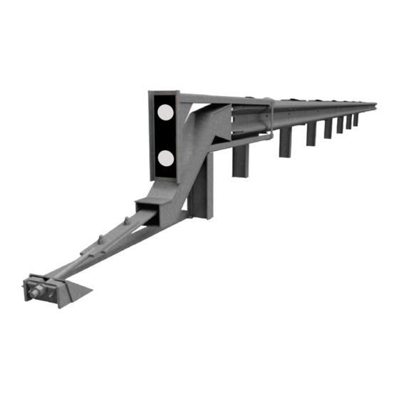
- Page 1 SoftStop ® Tangent End Terminal Product Manual Release 06/19 www.ingalcivil.co.nz...
- Page 2 SoftStop ® Tangent End Terminal The SoftStop® System Tangent End Terminal (“SoftStop® System”) has been tested to American Association of State and Highway Transportation O cials (“AASHTO”) Manual For Assessing Safety Hardware (“MASH”) criteria, as a Test Level 1, 2, &...
-
Page 3: Customer Service Contacts
SoftStop ® Tangent End Terminal Customer Service Contacts Ingal Civil Products is committed to the highest level of customer service. Feedback regarding the SoftStop™ End Terminal, its assembly procedures, supporting documentation, and performance is always welcome. Additional information can be obtained from the contact information below: Ingal Civil Products Corporate Contacts Telephone 09 920 6838 (Within New Zealand) - Page 4 SoftStop ® Tangent End Terminal 1.0 Introduction The SoftStop® System contains a SoftStop® Impact The SoftStop® System is a tangent, single-sided, energy- Head, SoftStop® Anchor Rail, SoftStop® Anchor Post absorbing, redirective and gating end terminal system. (Post 0), SoftStop® Angle Strut, two (2) Steel Yielding The SoftStop®...
- Page 5 SoftStop ® Tangent End Terminal The SoftStop® System can be assembled in a MASH Test Level 1, Test Level 2 or Test Level 3 con guration. * Before installation, ensure the variant of highway safety barrier is accepted for use by the nal asset owner. SoftStop Assembly Con gurations Test Level Design Speed...
-
Page 6: Inspection Of Shipment
SoftStop ® Tangent End Terminal 2.0 Inspection of Shipment Before assembling the SoftStop® System, carefully unpack and inspect all components for signs of damage. Check the received parts against the packing list supplied with the system to verify that all parts were received. If parts are damaged or missing from the shipment or unspeci ed parts were part of the shipment, do not attempt to assemble the system;... - Page 7 SoftStop ® Tangent End Terminal ID: A ID: A PN: 15208A PN: 15208A ID: B ID: B PN: 15200G PN: 15200G ID: C ID: C PN: 11G PN: 11G ID: A PN: 15208A ID: B PN: 15200G ID: C PN: 11G ID: A ID: A PN: 15208A...
- Page 8 ID: N ID: N PN: 15202G ID: N PN: 15202G PN: 15202G ID: O ID: O PN: 105285G ID: O PN: 105285G PN: 105285G ID: P ID: P PN: 105286G PN: 105286G ID: P PN: 105286G ID: N PN: 15202G ID: N ID: N PN: 15202G...
-
Page 9: Recommended Tools
SoftStop ® Tangent End Terminal 3.0 Recommended Tools Documentation Miscellaneous • Assembly Manual (Most Current Version) • Traffic Control Equipment • System Drawing (Most Current Version) • SAE Combination Wrench Set • Socket Set & Socket Wrench Personal protective equipment (PPE) • Hammer • Safety Glasses • Chalk Line • Work Gloves • Tape Measure • Safety-Toe Shoes • Marking Paint and Pen • Back Protection • Straight Edge • Hard Hat • Level... - Page 10 SoftStop ® Tangent End Terminal Figure 1: Preferred Grading (not to scale) Figure 2: Alternative Grading (not to scale) 5.0 SoftStop® System O set O set Requirements Within A Curve Requirements When the guardrail is terminated within a curve (convex or concave) and a SoftStop®...
- Page 11 SoftStop ® Tangent End Terminal Figure 3: Entire Length of System Convex Curve For radii of 198 m or greater (flatter), the offset is 0 m to 610 mm. For radii of 198 m or greater (flatter), the offset is 0 m to 610 mm. Concave Curve Concave Curve For radii between 152 m and 228 m, the offset is 0 m to 457 mm. For radii greater (flatter) than 228 m, the offset is 0 m For radii between 152 m and 228 m, the offset is 0 m to 457 mm. For radii greater (flatter) than 228 m, the offset is 0 m to 610 mm.
- Page 12 SoftStop ® Tangent End Terminal 6.0 SoftStop® System Post Placement The SoftStop® System posts may be inserted into the soil using an auger or impact hammer pile driver used for the placement of guardrail posts. If an auger is used, ensure Danger: Ensure all above &...
- Page 13 state/ specifying agency gu idelines. If rock is encou ntered at post locations 2- 8, refer to the local specifying agency gu idelines and the If rock is encou ntered at post locations 2- 8, refer to the local specifying agency gu idelines and the SoftStop AASHTO Roadside Design Gu ide for req u irements for emb edment depth into the rock and siz e of the ®...
- Page 14 SoftStop ® Tangent End Terminal SoftStop® System Anchor Post (Post 0) Placement The SoftStop® System Anchor Post (10007543) is the rst post of the SoftStop® System and is designated as Post 0. The SoftStop®System Anchor Post is to be assembled plumb and oriented with the front side of post facing towards the upstream end.
- Page 15 SoftStop ® Tangent End Terminal SoftStop® System Impact Head S o f t S top S ystem I mpact H ead ® The SoftStop® Impact Head (10007538) component is symmetrical and can be assembled on the left or right shoulder. The SoftStop Impact Head ( 15208A) component is symmetrical and can b e assemb led on the left or ®...
- Page 16 SoftStop ® Tangent End Terminal 7.0 TEST LEVEL 3 ASSEMBLY STEPS Important: Always use safety precautions when performing assembly, maintenance, repair and/or moving heaving equipment. Ensure proper personal protective equipment (PPE) is worn. Failure to follow this warning could result in serious injury or death. Release 06/19...
-
Page 17: Installation Procedure
SoftStop ® Tangent End Terminal 8.0 INSTALLATION PROCEDURE STEP 1 System Line Post Assembly (Posts 3-8) PARTS INSTRUCTIONS 10007540 6 EA 1. Assemble all parts in the con guration & orientation as shown in the above diagram. 2. The SoftStop® System must be attached to a w-beam guardrail that has been properly transitioned to 787 mm rail height per state/specifying agency (see Appendix for transition drawing example). - Page 18 SoftStop ® Tangent End Terminal STEP 2 Post Assembly (Posts 0-2) PARTS INSTRUCTIONS 10001402 1 EA 1. Assemble all parts in the con guration & orientation shown above. 10007539 1 EA 2. Ensure proper o set for Post 0 (Part D) and Post 1 (Part E) is as shown on dimension above and on the Post Displacement Diagram (page 30).
- Page 19 SoftStop ® Tangent End Terminal STEP 3 O set Block Assembly (Posts 3-8) PARTS INSTRUCTIONS 10001397 6 EA 1. Assemble all parts in the con guration & orientation shown above. 2. Attach (1 EA) O set Block (Part H) on tra c side of Posts 3-8. The O set Block is equipped with a self-hanging mounting tab.
- Page 20 SoftStop ® Tangent End Terminal STEP 4 O set Block Assembly (Post 2) PARTS INSTRUCTIONS 10001397 1 EA 10001300 1 EA 1. Assemble all parts in the con guration & orientation shown above. 10001299 2. Attach (1 EA) O set Block (Part H) on tra c side of Post 2. The O set Block is equipped with a self-hanging mounting tab.
- Page 21 SoftStop ® Tangent End Terminal STEP 5 3.81m System Rail Assembly (Post 3-8) PARTS INSTRUCTIONS 10007537 3 EA 10001300 6 EA 1. Assemble all parts in the con guration & orientation shown above. 10007550 24 EA 2. Place all System Rail panels (Part C) on the tra c side of the posts and lap all System Rail panels in the direction of tra c as shown above using shown 10001299 30 EA hardware.
- Page 22 SoftStop ® Tangent End Terminal STEP 6 Anchor Rail Assembly PARTS INSTRUCTIONS 10007536 1 EA 10007550 8 EA 1. Assemble all parts in the con guration & orientation shown above. 10001299 8 EA 2. Place SoftStop® Anchor Rail (Part B) on the tra c side and lap in the direction of tra c as shown above using shown hardware.
- Page 23 SoftStop ® Tangent End Terminal STEP 7 Impact Head Assembly PARTS INSTRUCTIONS 10007538 1 EA 1. Assemble all parts in the con guration & orientation shown above. 10007553 1 EA 2. Mechanically push the SoftStop® Impact Head (Part A) until its Connection 10007554 2 EA Bracket rests against Post 1 and a minimum 457 mm of the SoftStop®...
- Page 24 SoftStop ® Tangent End Terminal STEP 8 Anchor Paddle Assembly PARTS INSTRUCTIONS 10007542 1 EA 1. Assemble all parts in the con guration & orientation shown above. 10001284 4 EA 2. Flatten the exposed Anchor Rail, line up holes using an alignment tool onto the 10001285 2 EA rail and insert the hex bolts and bottom washers as shown above.
- Page 25 SoftStop ® Tangent End Terminal STEP 9 Anchor Post Assembly (Post 0) PARTS INSTRUCTIONS 10007554 4 EA 1. Assemble all parts in the con guration & orientation shown above. 10007555 2 EA 2. Place the rod portion of the SoftStop® Anchor Paddle in the notch of Post 0. 10007549 1 EA 3.
- Page 26 SoftStop ® Tangent End Terminal STEP 10 Angle Strut Assembly (Posts 0-1) Note: Items below grade shown for clarity. PARTS INSTRUCTIONS 10001299 2 EA 1. Assemble all parts in the con guration & orientation shown above. 10007095 4 EA 2. It will be necessary to make a shallow valley/trough between Post 0 & 1 for the SoftStop®...
- Page 27 SoftStop ® Tangent End Terminal STEP 11 Delineation Assembly PARTS INSTRUCTIONS BY OTHERS 1. Assemble all parts in the con guration & orientation shown above. Note: Manufacturer suggests that user provide delineation (re ective sheeting) of the terminal. WARNINGS Use only Trinity Highway parts that are speci ed herein for the SoftStop®...
- Page 28 SoftStop ® Tangent End Terminal 9.0 SoftStop Installation Checklist Customer: Project: Barrier ID: Terminal Type: MASH TL2 MASH TL3 Checked By: Signed: Date: Is the assembled Anchor post installed in the correct orientation with the sloped side facing the terminal and within tolerance (102 +0/-6 mm measured from ground level to the top of the Anchor Angles) Is Anchor Keeper Plate installed in correct con guration on Anchor post (Step 9) Have Anchor post Angles been correctly bolted to the Anchor post (Step 10)
-
Page 29: Maintenance And Repair
SoftStop ® Tangent End Terminal 10.0 Maintenance and Repair steel surface. Depending on the section thickness of the steel, the actual steel surface temperature may not Except for repairs due to impacts, there is virtually no exceed 350°C. maintenance required for the system. It is recommended Typically, the bushfire flame duration and intensity are that annual inspections be performed to ensure the not high enough to compromise the structural strength... - Page 30 SoftStop System Test Level 3 (Posts 0-8) – Post Placement Diagram 2000 N O T ES : N O T ES : 1. P ost 0-6 part of S of tS top® S y stem T L2 1. P ost 0-6 part of S of tS top® S y stem T L2 2.
- Page 31 SoftStop System Test Level 2 (Posts 0-6) – Post Placement Diagram 2000 N O T ES : 1. P ost 0-4 part of S of tS top® S y stem T L1 2. P ost 5 is f irst post of longitu dinal w -b eam sy stem (not inclu ded w ith S of tS top® S y stem) 3 .
- Page 32 SoftStop System Test Level 1 (Posts 0-4) – Post Placement Diagram 2000 N O T ES : N O T ES : 1. P ost 0-6 part of S of tS top® S y stem T L2 1. P ost 0-6 part of S of tS top® S y stem T L2 2.
- Page 33 PARTS LIST NOTE: PART NO. QTY. DESCRIPTION INSTALL SoftStop PARALLEL TO ROADWAY. 10007537 SoftStop Terminal Guardrail 000011 WHEN OFFSET IS REQUIRED BY DESIGN ENGINEER, MASH TEST LEVEL 3 (TL-3) SoftStop TERMINAL 10007540 SoftStop Line Post 1830mm 000533 SEE SoftStop MANUAL FOR REQUIREMENTS. ...
- Page 34 For more information contact us on the web www.ingalcivil.co.nz Auckland Head O ce: Sydney 57-65 Airds Road, Minto, NSW 2566 12 O enhauser Drive, East Tamaki, Ph: +61 2 9827 3333 Auckland 2013, New Zealand Fax: +61 2 9827 3300 Ph: 09 273 9820 Free call (within Australia): Email: sales@ingalcivil.co.nz...