Table of Contents
Advertisement
Quick Links
Advertisement
Table of Contents

Related Manuals for Supermicro Supero C7Z97-M


Summary of Contents for Supermicro Supero C7Z97-M
- Page 1 C7Z97-M C7Z97-MF USER’S MANUAL Revision 1.0a...
- Page 2 This product, including software and documenta- tion, is the property of Supermicro and/or its licensors, and is supplied only under a license. Any use or reproduction of this product is not allowed, except as expressly permitted by the terms of said license.
-
Page 3: Manual Organization
Preface Preface This manual is written for system integrators, PC technicians and knowledgeable PC users. It provides information for the installation and use of the C7Z97-M/MF motherboard. Manual Organization Chapter 1 describes the features, specifications and performance of the motherboard, and provides detailed information on the Intel Z97 Express chipset. -
Page 4: Checklist
Supermicro C7Z97-M Series Motherboard User’s Manual Checklist Congratulations on purchasing your computer motherboard from an ac- knowledged leader in the industry. Supermicro boards are designed with the utmost attention to detail to provide you with the highest standards in quality and performance. -
Page 5: Standardized Warning Statements
The following statements are industry-standard warnings, provided to warn the user of situations which have the potential for bodily injury. Should you have questions or experience difficulty, contact Supermicro's Technical Support department for assistance. Only certified technicians should attempt to install or configure components. -
Page 6: Product Disposal
Supermicro C7Z97-M Series Motherboard User’s Manual ¡Advertencia! Existe peligro de explosión si la batería se reemplaza de manera incor- recta. Reemplazar la batería exclusivamente con el mismo tipo o el equivalente recomendado por el fabricante. Desechar las baterías gasta- das según las instrucciones del fabricante. - Page 7 Standardized Warning Statements 製品の廃棄 この製品を廃棄処分する場合、 国の関係する全ての法律 ・ 条例に従い処理する必要が あり ます。 警告 本产品的废弃处理应根据所有国家的法律和规章进行。 警告 本產品的廢棄處理應根據所有國家的法律和規章進行。 Warnung Die Entsorgung dieses Produkts sollte gemäß allen Bestimmungen und Gesetzen des Landes erfolgen. ¡Advertencia! Al deshacerse por completo de este producto debe seguir todas las leyes y reglamentos nacionales.
-
Page 8: Contacting Supermicro
Supermicro C7Z97-M Series Motherboard User’s Manual Contacting Supermicro Headquarters Address: Super Micro Computer, Inc. 980 Rock Ave. San Jose, CA 95131 U.S.A. Tel: +1 (408) 503-8000 Fax: +1 (408) 503-8008 Email: marketing@supermicro.com (General Information) support@supermicro.com (Technical Support) www.supermicro.com Site: Europe Address: Super Micro Computer B.V. -
Page 9: Where To Find More Information
For your system to work properly, please follow the links below to download all necessary drivers/utilities and the user's manual for your motherboard. SMCI product manuals: http://www.supermicro.com/support/manuals/ Product Drivers and utilities: ftp://ftp.supermicro.com/ If you have any questions, please contact our support team at support@ supermicro.com. -
Page 10: Table Of Contents
Supermicro C7Z97-M Series Motherboard User’s Manual Table of Contents Preface Manual Organization ................iii Checklist ..................iv Conventions Used in the Manual ............iv Standardized Warning Statements ............v Battery Handling ............... v Product Disposal ...............vi Contacting Supermicro ..............viii Where to Find More Information............ix... - Page 11 Table of Contents Removing the Heatsink ............2-8 Installing DDR3 Memory ............2-9 DIMM Installation ..............2-9 Removing Memory Modules ............. 2-9 Memory Support ..............2-10 Memory Population Guidelines ..........2-10 Memory Population Guidelines ..........2-11 Motherboard Installation ............2-12 Tools Needed ...............
- Page 12 Supermicro C7Z97-M Series Motherboard User’s Manual Standby Power Header (STBY1) ......... 2-26 TPM Header/Port 80 Header ..........2-26 Front Panel Audio Header (AUDIO FP) ........ 2-27 OC Front Panel (OC FRONT PANEL) ........2-27 Jumper Settings ..............2-28 Explanation of Jumpers ............2-28 LAN1 Enable/Disable (JPL1) ..........
- Page 13 Table of Contents Technical Support Procedures ..........3-3 Frequently Asked Questions ............ 3-4 Battery Removal and Installation ..........3-5 Battery Removal ..............3-5 Proper Battery Disposal ............3-5 Returning Motherboard for Service ........... 3-6 Battery Installation ..............3-6 Chapter 4 BIOS Introduction ................
- Page 14 Supermicro C7Z97-M Series Motherboard User’s Manual CPU AES ................. 4-12 Boot Performance Mode ............ 4-13 Power Management .............. 4-13 EIST ................4-13 Turbo Mode ..............4-13 CPU C States ..............4-16 Package C-State limit ............4-17 LakeTiny Feature .............. 4-17 Overclocking ...............
- Page 15 Table of Contents CPU Cache Adaptive/Override/Offset Voltage Target (mV) ..4-22 System Agent Voltage Offset (mV) ........4-22 CPU IOA Voltage Offset (mV) ..........4-22 CPU IOD Voltage Offset (mV) ..........4-22 PCH 1.05V Voltage ............4-22 PCH 1.5V Voltage ............. 4-22 Overclocking SVID and FIVR Options ........
- Page 16 Supermicro C7Z97-M Series Motherboard User’s Manual PCH-IO ................4-37 Wake on LAN ..............4-37 Azalia (HD Audio) ............4-37 Memory ................4-38 Memory Information............. 4-38 Memory Configuration ............4-40 Max TOLUD (Top of Low Usable DRAM) ....... 4-40 Enhanced Interleave Support ..........4-40 Rank Interlevel Support ............
- Page 17 Table of Contents IRQ Settings ..............4-46 4-9 Booting ................4-47 Boot Device Settings ............4-47 Boot Mode Select ............. 4-47 Boot Order #1~#15 ............4-47 Power Settings ..............4-48 Bootup Numlock State ............4-48 Quiet Boot ..............4-48 Fast Boot ................ 4-48 AddOn ROM Display Mode ..........
- Page 18 Supermicro C7Z97-M Series Motherboard User’s Manual 4-10 Management ............... 4-55 ACPI Settings ..............4-55 ACPI Sleep State ............. 4-55 Console Redirection Settings ..........4-56 COM1 ................. 4-56 Enable Console Redirection ..........4-56 Console Redirection Settings ..........4-56 Serial Port for Out-of-Band Management/Windows Emergency Management Services (EMS) ..........
- Page 19 Table of Contents Appendix A BIOS Error Beep Codes BIOS Error Beep Codes ............A-1 Appendix B Software Installation Instructions Installing Drivers ..............B-1 Configuring SuperDoctor ® III ..........B-2 Appendix C UEFI BIOS Recovery Instructions An Overview to the UEFI BIOS ..........C-1 How to Recover the UEFI BIOS Image (-the Main BIOS Block) ..
- Page 20 Supermicro C7Z97-M Series Motherboard User’s Manual Notes...
-
Page 21: Introduction
DT processor, in an LGA 1150 (H3) socket. With the Intel® Z97 Express chipset built in, the C7Z97-M/MF motherboard offers substantial system performance and storage capability for overclocking platforms in a sleek package. Please refer to our website (http://www.supermicro.com/prod- ucts/) for processor and memory support updates. 1-2 Chipset Overview Intel Z97 Express Chipset Features •... -
Page 22: Motherboard Features
Supermicro C7Z97-M Series Motherboard User’s Manual 1-3 Motherboard Features Single 4th Generation Intel® Core™ i7/i5/i3 DT processor, LGA1150 socket. Four (4) Memory slots support up to 32 GB of Memory DDR3 Unbuffered, Non-ECC 1066~3000(OC) MHz memory Dual-channel memory DIMM sizes... - Page 23 Chapter 1: Introduction One (1) Front Panel Audio Header One (1) SPDIF Out on the rear side of the chassis Super I/O Nuvoton NCT6776D 128 Mb AMI BIOS SPI Flash BIOS BIOS ® Plug and Play (PnP0, DMI 2.8.0, PCI 2.3, ACPI 1.0/2.0/3.0, USB Keyboard Power Configuration ACPI/ASPM Power Management Main Switch Override Mechanism...
-
Page 24: Special Features
Supermicro C7Z97-M Series Motherboard User’s Manual 1-4 Special Features Recovery from AC Power Loss Basic I/O System (BIOS) provides a setting for you to determine how the system will respond when AC power is lost and then restored to the system. You can choose for the system to remain powered off, (in which case you must press the power switch to turn it back on), or for it to automatically return to a power-on state. -
Page 25: System Resource Alert
Chapter 1: Introduction System Resource Alert This feature is available when the system is used with SuperDoctor III in the Windows OS environment or used with SuperDoctor II in Linux. SuperDoctor is used to notify the user of certain system events. For example, you can also configure SuperDoctor to provide you with warnings when the system temperature, CPU temperatures, voltages and fan speeds go beyond predefined thresholds. -
Page 26: Power Supply
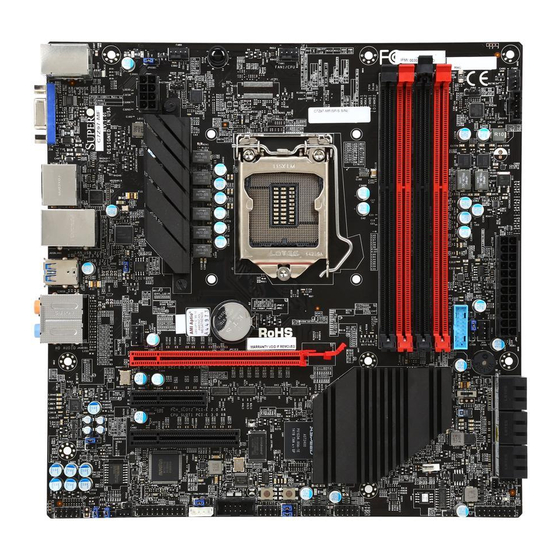
Supermicro C7Z97-M Series Motherboard User’s Manual 1-7 Power Supply As with all computer products, a stable power source is necessary for proper and reliable operation. It is even more important for processors that have high CPU clock rates. This motherboard accommodates 24-pin ATX power supplies. Although most power supplies generally meet the specifications required by the CPU, some are inadequate. - Page 27 Chapter 1: Introduction C7Z97-M/C7Z97-MF Motherboard Image Note: All graphics shown in this manual were based upon the latest PCB Revision available at the time of publishing of the manual. The motherboard you've received may or may not look exactly the same as the graphics shown in this manual.
- Page 28 Supermicro C7Z97-M Series Motherboard User’s Manual C7Z97-M/C7Z97-MF Motherboard Layout HDMI/DP USB 0/1 VGA(IPMI) USB 12/13 (3.0) HD AUDIO KB/MOUSE FAN5 JI2C1 USB 2/3 JI2C2 (3.0) JPL1 JPW2 C7Z97-M Rev. 1.00 BIOS LICENSE JBT1 DIMMA1 DIMMA2 DIMMB1 DIMMB2 USB8/9(3.0) JSD1 I-SATA0...
-
Page 29: Jumper Description
Chapter 1: Introduction C7Z97-M/C7Z97-MF Quick Reference HDMI/DP USB 0/1 VGA(IPMI) USB 12/13 (3.0) HD AUDIO KB/MOUSE FAN5 JI2C1 USB 2/3 JI2C2 (3.0) JPL1 JPW2 C7Z97-M Rev. 1.00 BIOS LICENSE JBT1 DIMMA1 DIMMA2 DIMMB1 DIMMB2 USB8/9(3.0) JSD1 I-SATA0 I-SATA1 I-SATA3 JPW1 FAN3 FAN2 I-SATA1... - Page 30 Supermicro C7Z97-M Series Motherboard User’s Manual Connector Description I/O Back Panel See Back Panel I/O Connectors, below right Audio FP Front Panel Audio Header Battery Onboard Battery COM1 COM1 Port Header Fan 1,2,3,4,5 System/CPU Fan Headers (Fan1: CPU Fan) Speaker/buzzer (Pins 1~4: External Speaker, Pins 3~4: Buzzer)
-
Page 31: Installation
Chapter 2: Installation Chapter 2 Installation 2-1 Installation Components and Tools Needed Screws Phillips-Head Screwdriver Intel LGA 1150 Processor DDR3 DIMMs PC Chassis Heatsink with Fan Power Supply Video Card (Optional) SATA/USB Optical Drive (Optional) SATA Hard Disk Drive... -
Page 32: Static-Sensitive Devices
Supermicro C7Z97-M Series Motherboard User’s Manual 2-2 Static-Sensitive Devices Electrostatic-Discharge (ESD) can damage electronic com ponents. To avoid damaging your system board, it is important to handle it very carefully. The following measures are generally sufficient to protect your equipment from ESD. -
Page 33: Processor And Heatsink Installation
CPU socket cap is in place and none of the socket pins are bent; otherwise, contact your retailer immediately. Refer to the Supermicro website for updates on CPU support. Installing the LGA1150 Processor 1. Press the load lever to release the load plate, which covers the CPU socket, from its locking position. - Page 34 Supermicro C7Z97-M Series Motherboard User’s Manual 2. Gently lift the load lever to open the load plate. Remove the plas- tic cap. 3. Use your thumb and your index finger to hold the CPU at the North center edge and the South center edge of the CPU.
- Page 35 Chapter 2: Installation 5. Do not rub the CPU against the surface or against any pins of the socket to avoid damaging the CPU or the socket.) 6. With the CPU inside the socket, inspect the four corners of the CPU to make sure that the CPU is properly installed.
-
Page 36: Installing An Active Cpu Heatsink With Fan
Supermicro C7Z97-M Series Motherboard User’s Manual Installing an Active CPU Heatsink with Fan 1. Locate the CPU Fan power con- nector on the motherboard. (Refer to the layout on the right for the CPU Fan location.) 2. Position the heatsink so that... - Page 37 Chapter 2: Installation between the fan wires and the fins of the heatsink. 7. Align the four heatsink fasteners with the mounting holes on the motherboard. Gently push the pairs of diagonal fasteners (#1 & #2, and #3 & #4) into the mounting holes until you hear a click.
-
Page 38: Removing The Heatsink
Supermicro C7Z97-M Series Motherboard User’s Manual Removing the Heatsink Attention! We do not recommend that the CPU or the heatsink be removed. However, if you do need to remove the heatsink, please follow the instructions below to re- move the heatsink and to prevent damage done to the CPU or other components. -
Page 39: Installing Ddr3 Memory
Chapter 2: Installation 2-4 Installing DDR3 Memory Note: Check the Supermicro website for recommended memory modules. Attention! Exercise extreme care when installing or removing DIMM modules to prevent any possible damage. DIMM Installation 1. Insert the desired number of HDMI/DP... -
Page 40: Memory Support
Supermicro C7Z97-M Series Motherboard User’s Manual Memory Support Towards the CPU DIMMA1 DIMMA2 (Red Slot) DIMMB1 DIMMB2 (Red Slot) Towards the edge of the motherboard The C7Z97-M/MF supports up to 32GB of Unbuffered (UDIMM) DDR3 Non-ECC 1066~3000(OC) MHz in 4 memory slots. Populating these... - Page 41 Chapter 2: Installation duced when 4 GB of RAM is used. The reduction in memory availability is disproportional. See the following table for details. For Microsoft Windows users: Microsoft implemented a design change in the Windows XP with Service Pack 2 (SP2) and Win- dows Vista.
-
Page 42: Motherboard Installation
Supermicro C7Z97-M Series Motherboard User’s Manual 2-5 Motherboard Installation All motherboards have standard mounting holes to fit different types of chassis. Make sure that the locations of all the mounting holes for both motherboard and chassis match. Although a chassis may have both plas- tic and metal mounting fasteners, metal ones are highly recommended because they ground the motherboard to the chassis. -
Page 43: Installing The Motherboard
Chapter 2: Installation Installing the Motherboard 1. Install the I/O shield into the back of the chassis. 2. Locate the mounting holes on the motherboard. (See the previous page.) 3. Locate the matching mounting holes on the chassis. Align the mounting holes on the motherboard against the mounting holes on the chassis. -
Page 44: Connectors/Io Ports
Supermicro C7Z97-M Series Motherboard User’s Manual 2-6 Connectors/IO Ports The I/O ports are color coded in conformance with the PC 99 specification. See the figure below for the colors and locations of the various I/O ports. Back I/O Panel HDMI/DP... -
Page 45: Universal Serial Bus (Usb)
Chapter 2: Installation Universal Serial Bus (USB) Two Universal Serial Bus 2.0 ports (0/1) and four USB 3.0 ports (2/3,12/13) are located on the I/O back panel. In addition, two USB 2.0 headers (four ports: 4/5, 6/7), and one USB 3.0 header (two ports: 14/15) are also located on the motherboard to provide front chassis access using USB cables (not included). -
Page 46: Ethernet / Ipmi Port
Supermicro C7Z97-M Series Motherboard User’s Manual Ethernet / IPMI Port LAN Ports Pin Definition One Gigabit Ethernet ports (LAN1) is Pin# Definition located next to the HD Audio Connector P2V5SB SGND on the I/O Backpanel to provide network connections. These ports accept RJ45... -
Page 47: Hdmi Port
Chapter 2: Installation HDMI Port One HDMI (High-Definition Multimedia Interface) is located next to the VGA port on the I/O backpanel. This con- nector is used to display both high definition video and digital sound through an HDMI capable display, us- ing a single HDMI cable (not included). -
Page 48: Front Control Panel
JF1 contains header pins for various buttons and indicators that are normally located on a control panel at the front of the chassis. These connectors are designed specifically for use with Supermicro chassis. See the figure below for the descriptions of the front control panel buttons and LED indicators. -
Page 49: Front Control Panel Pin Definitions
Chapter 2: Installation Front Control Panel Pin Definitions Power LED Power LED Pin Definitions (JF1) The Power LED connection is located on Pin# Definition pins 15 and 16 of JF1. Refer to the table on the right for pin definitions. Ground HDD LED HDD LED... -
Page 50: Reset Button
Supermicro C7Z97-M Series Motherboard User’s Manual Reset Button Reset Button The Reset Button connection is located Pin Definitions (JF1) on pins 3 and 4 of JF1. Attach it to a Pin# Definition hardware reset switch on the computer Reset case to reset the system. Refer to the Ground table on the right for pin definitions. -
Page 51: Connecting Cables
Chapter 2: Installation 2-7 Connecting Cables This section provides brief descriptions and pin-out definitions for on- board headers and connectors. Be sure to use the correct cable for each header or connector. ATX Power 24-pin Connector ATX Main PWR & CPU PWR Pin Definitions (JPW1) Connectors (JPW1 &... -
Page 52: Fan Headers (Fan 1 ~ Fan 5)
Supermicro C7Z97-M Series Motherboard User’s Manual Fan Headers (Fan 1 ~ Fan 5) Fan Header Pin Definitions The C7Z97-M/MF has five fan headers Pin# Definition (Fan 1~Fan 5). These fans are 4-pin fan Ground (Black) headers. Although pins 1-3 of the fan 2.5A/+12V... -
Page 53: Internal Buzzer (Sp1)
Chapter 2: Installation Internal Buzzer (SP1) Internal Buzzer Pin Definition The Internal Buzzer (SP1) can be used Pin# Definitions to provide audible indications for various Pin 1 Pos. (+) Beep In beep codes. See the table on the right Pin 2 Neg. -
Page 54: Onboard Power Led (Jled1)
Supermicro C7Z97-M Series Motherboard User’s Manual Onboard Power LED (JLED1) Onboard PWR LED Pin Definitions An onboard Power LED header is located Pin# Definition at next to the SATA ports. This Power LED header is connected to Front Control No Connection... -
Page 55: Dom Pwr Connector (Jsd1)
Chapter 2: Installation DOM PWR Connector (JSD1) DOM PWR Pin Definitions The Disk-On-Module (DOM) power con- Pin# Definition nector, located next to the SATA ports, provides 5V (Gen1/Gen) power to a solid Ground state DOM storage device connected to Ground one of the SATA ports. -
Page 56: Standby Power Header (Stby1)
Supermicro C7Z97-M Series Motherboard User’s Manual Standby Power Header (STBY1) Standby Power Pin Definitions The Standby Power header is located Pin# Definition at STBY1 on the motherboard. See the +5V Standby table on the right for pin definitions. Ground Wake-up... -
Page 57: Front Panel Audio Header (Audio Fp)
Chapter 2: Installation Front Panel Audio Header (AUDIO 10-in Audio Pin Definitions Pin# Signal A 10-pin Audio header is supported on Microphone_Left the motherboard. This header allows you Audio_Ground to connect the motherboard to a front Microphone_Right panel audio control panet, if needed. Audio_Detect Connect an audio cable to the audio header to use this feature (not supplied). -
Page 58: Jumper Settings
Supermicro C7Z97-M Series Motherboard User’s Manual 2-8 Jumper Settings Explanation of Jumpers To modify the operation of the mother- board, jumpers can be used to choose between optional settings. Jumpers create shorts between two pins to change the function of the connector. -
Page 59: Clear Cmos (Jbt1), (S8)
Chapter 2: Installation Clear CMOS (JBT1), (S8) JBT1 and the S8 Button is used to clear the saved system setup configu- ration stored in the CMOS chip. For JBT1, to clear the contents of the CMOS, completely shut down the system, remove the AC power cord and then short JBT1 with a metallic object such as a screwdriver. -
Page 60: Audio Enable (Jpac1)
Supermicro C7Z97-M Series Motherboard User’s Manual Audio Enable (JPAC1) Audio Enable/Disable Jumper Settings JPAC1 allows you to enable or disable the Both Jumpers Definition onboard audio support. The default posi- Pins 1-2 Enabled tion is on pins 1 and 2 to enable onboard... -
Page 61: Usb Wake-Up (Jpusb 1/2)
Chapter 2: Installation USB Wake-Up (JPUSB 1/2) USB Wake-Up Jumper Settings Use jumper JPUSB to activate the "wake- Jumper Setting Definition up" function of the USB ports by pressing Pins 1-2 Enabled a key on a USB keyboard or clicking the Pins 2-3 Disabled (Default) USB mouse connected. -
Page 62: Manufacturing Mode (Jpme2)
Supermicro C7Z97-M Series Motherboard User’s Manual Manufacturing Mode (JPME2) Close Pin 2 and Pin 3 of Jumper JPME2 Manufacture Mode (JPME2) Jumper Settings to bypass SPI flash security and force Pin# Definition the system to operate in Manufactur- Normal (Default) ing Mode, allowing the user to flash the... -
Page 63: Bios Recovery Switch (Jbr1)
Chapter 2: Installation BIOS Recovery Switch (JBR1) BIOS Recovery (JBR1) Jumper Settings The BIOS Recovery Switch (JBR1) is used State Definition to enable or disable the BIOS Recovery Normal (Default) feature of the motherboard. Slide the Recover switch from the default position to begin the recovery process. -
Page 64: Onboard Indicators
Supermicro C7Z97-M Series Motherboard User’s Manual 2-9 Onboard Indicators LAN 1 LEDs GLAN 1/2 Activity Indicator LED Settings One LAN port (LAN 1) is located on the Color Status Definition I/O back panel of the motherboard. Yellow Flashing Active This LAN port has two LEDs. The yellow... -
Page 65: Ipmi Heartbeat (Ledm1)
Chapter 2: Installation IPMI Heartbeat (LEDM1) IPMI Heartbeat LED Status The IPMI Heartbeat LED dis- Status Definition plays the status of the IPMI / System Off BMC (Baseboard Management Blinking IPMI/BMC is on and work- Controller). ing normally A. IPMI Heartbeat HDMI/DP USB 0/1 VGA(IPMI) -
Page 66: Sata Connections
Supermicro C7Z97-M Series Motherboard User’s Manual 2-10 SATA Connections SATA Connections (I-SATA0~I-SATA5) Six Serial ATA (SATA) 3.0 connectors (I-SATA 0~5) are supported on the board. The I-SATA 3.0 ports are supported by the Intel Z97 PCH chip (supports RAID 0,1,5,10). These Serial Link connections provide faster data transmission than legacy Parallel ATA. -
Page 67: The Oc Front Control Panel (Optional)
Chapter 2: Installation 2-10 The OC Front Control Panel (Optional) The OC (Over-Clocking) Front Control Panel has Six (6) control buttons, switches and one USB port. OC-1 OC-2 OC-3 BIOS1 BIOS2 Clean CMOS Boot BIOS Bios Recovery & Reset Switch Over-Clocking Buttons (OC1, OC2, OC3) Press these buttons to activate the over-clocking feature of the motherboard. -
Page 68: Installing The Oc Front Control Panel
Supermicro C7Z97-M Series Motherboard User’s Manual Installing the OC Front Control Panel The OC Front Control Panel is designed to fit into an external 5.25-inch external drive bay of a desktop-style or tower-style computer chassis. Make sure that the appropriate type of screws are used. -
Page 69: Troubleshooting
Chapter 3: Troubleshooting Chapter 3 Troubleshooting 3-1 Troubleshooting Procedures Use the following procedures to troubleshoot your system. If you have followed all of the procedures below and still need assistance, refer to the ‘Technical Support Procedures’ and/or ‘Returning Merchandise for Service’ section(s) in this chapter. -
Page 70: No Video
Supermicro C7Z97-M Series Motherboard User’s Manual No Video 1. If the power is on, but you have no video--in this case, you will need to re- move all the add-on cards and cables first. 2. Use the speaker to determine if any beep codes exist. (Refer to Appendix A for details on beep codes.) -
Page 71: Technical Support Procedures
Before contacting Technical Support, please make sure that you have followed all the steps listed below. Also, Note that as a motherboard manufacturer, Supermicro does not sell directly to end users, so it is best to first check with your distributor or reseller for troubleshooting services. -
Page 72: Frequently Asked Questions
Supermicro C7Z97-M Series Motherboard User’s Manual 3-3 Frequently Asked Questions Question: What type of memory does my motherboard support? Answer: The C7Z97-M/MF supports up to 32GB of unbuffered Non-ECC DDR3 SDRAM, 1066~3000 MHz (OC). See Section 2-4 for details on installing memory. -
Page 73: Battery Removal And Installation
Important: The SPI BIOS chip installed on this motherboard is not removable. To repair or replace a damaged BIOS chip, please send your motherboard to RMA at Supermicro for service. Question: I think my BIOS is corrupted. How can I recover my BIOS? Answer: Please see Appendix C-BIOS Recovery for detailed instructions. -
Page 74: Returning Motherboard For Service
Supermicro C7Z97-M Series Motherboard User’s Manual Battery Installation 1. To install an onboard battery, follow the steps 1& 2 above and con- tinue below: 2. Identify the battery's polarity. The positive (+) side should be fac- ing up. 3. Insert the battery into the battery holder and push it down until you hear a click to ensure that the battery is securely locked. -
Page 75: Introduction
Chapter 4: AMI BIOS Chapter 4 BIOS 4-1 Introduction This chapter describes the AMI BIOS Setup Utility for the C7Z97-M/MF. The ROM BIOS is stored in a Flash EEPROM and can be easily updated. This chapter describes the basic navigation of the AMI BIOS Setup Util- ity setup screens. -
Page 76: How To Change The Configuration Data
Supermicro C7Z97-M Series Motherboard User’s Manual The AMI BIOS GUI Setup Utility uses a mouse pointer navigation system similar to standard graphical user interfaces. Hover and click an icon to select a section, click a down arrow to select from an options list. -
Page 77: Setup Home
Chapter 4: AMI BIOS 4-2 Setup Home The first screen of the AMI BIOS GUI Setup Utility is the Setup Home screen. You can always return to the Setup Home screen by clicking the Home icon on the top of the screen. The Setup Home screen is shown below. - Page 78 Supermicro C7Z97-M Series Motherboard User’s Manual By default, some advanced menu options are hidden from display (in the CPU Overclocking section for example). Clicking Expert Mode ON or OFF will display or hide these options from the menu. In this chapter, all Expert Mode option items are bold and underlined.
-
Page 79: Load Optimized Defaults
Chapter 4: AMI BIOS Load Optimized Defaults To set this feature, select Load Optimized Defaults from the Save & Load menu and press <Enter>. These are factory settings designed for maxi- mum system performance but not for maximum stability. Save All Settings Only When you have completed the system configuration changes, select this option to save all changes made. -
Page 80: System Information
Supermicro C7Z97-M Series Motherboard User’s Manual 4-3 System Information The System Information Screen displays the motherboard's configuration. Motherboard The following information are displayed in this section: • Motherboard Model Name - C7Z97-M/MF. • BIOS Version - this item displays the BIOS version number. -
Page 81: Cpu
Chapter 4: AMI BIOS The following information are be displayed in this section: • Type and Speed of CPU - indicates the brand, model name, model number of the CPU and it's rated clock speed. • CPU Signature - displays the unique signature embedded in the CPU. •... -
Page 82: Memory
Supermicro C7Z97-M Series Motherboard User’s Manual Memory The following information are be displayed in this section: • Total Memory - shows the total detected system memory. • Memory Frequency - displays the system memory's detected speed. -
Page 83: Pch
Chapter 4: AMI BIOS The following information are be displayed in this section: • Name - displays the name of the PCH chip (if detected). • PCH SKU - this item displays the part number of the PCH chip. • Stepping- shows the PCH chip's stepping number. -
Page 84: Processor (Cpu)
Supermicro C7Z97-M Series Motherboard User’s Manual 4-4 Processor (CPU) Set all options for the processor in this section. Information The following CPU information will be displayed: • CPU Signature - displays the unique signature emebedded in CPU. • Microcode Patch - displays the CPU's microcode patch version. -
Page 85: Performance
Chapter 4: AMI BIOS • L1 Data Cache - indicates if Level 1 cache is supported. • L1 Code Cache - displays if Level 1 code cache is supported. • L2 Cache - indicates if Level 2 cache is supported. •... -
Page 86: Limit Cpuid Maximum
Supermicro C7Z97-M Series Motherboard User’s Manual Limit CPUID Maximum Select Enabled to set the maximum CPU ID value and to boot a legacy OS that cannot support processors with extended CPUID functions. The options are Enabled and Disabled (for the Windows OS). -
Page 87: Boot Performance Mode
Chapter 4: AMI BIOS Boot Performance Mode This option enables the selection of the default CPU performance during system boot. The options are Max Non-Turbo Performance, Max Bat- tery and Turbo Performance. Power Management EIST EIST (Enhanced Intel SpeedStep Technology) allows the system to automatically adjust processor voltage and core frequency in an effort to reduce power consumption and heat dissipation. - Page 88 Supermicro C7Z97-M Series Motherboard User’s Manual CPU Power Limit1 Use this feature to set the power limit for CPU1. Use the number keys on your keyboard to enter the value. Enter 0 to use the manufacturer's default setting. CPU Power Limit1 Time This item allows the user to determine how long CPU1 should oper- ate at the power limit set by the user for the item above.
- Page 89 Chapter 4: AMI BIOS DDR Power Limit1 Use this feature to set the power limit for DDR Memory Module 1. Use the number keys on your keyboard to enter the value. Enter 0 to use the manufacture's default setting. DDR Power Limit1 Time This item allows the user to determine how long Memory Module 1 should operate at the power limit set by the item above.
-
Page 90: Cpu C States
Supermicro C7Z97-M Series Motherboard User’s Manual CPU C States C-States architecture, a processor power management platform devel- oped by Intel, can further reduce power consumption from the basic C1 (Halt State) state that blocks clock cycles to the CPU. Select Enabled for CPU C Sates support. -
Page 91: Package C-State Limit
Chapter 4: AMI BIOS C7 Latency (Available when "CPU C States" is set to Enabled) Select Short to set a short delay time(period) during which the BIOS reports CPU C7 State (ACPI C3) to the operating system. Select Long to set a long delay time(period) during which the BIOS reports CPU C7 State (ACPI C3) to the operating system. -
Page 92: Overclocking
Supermicro C7Z97-M Series Motherboard User’s Manual 4-5 Overclocking Set all options for the Overclocking in this section. CPU Overclocking Load SMC CPU OC Setting This item has optimized pre-configured overclock settings. Select one to activate. The options are Manual, 4.2GHz, 4.3GHz, 4.4GHz, 4.5GHz, 4.6GHz, 4.7GHz, and 4.8GHz. -
Page 93: 3-Core Ratio Limit
Chapter 4: AMI BIOS 3-Core Ratio Limit This increases (multiplies) 3 clock speeds in the CPU core in relation to the bus speed when three CPU cores are active. Press "+" or "-" on your keyboard to change the value. Enter 0 to use the manufacturer's default setting. -
Page 94: Cpu Power Setting
Supermicro C7Z97-M Series Motherboard User’s Manual CPU Power Setting Enhanced Intel SpeedStep Technology Enhanced Intel SpeedStep Technology (EIST) allows the system to automatically adjust processor voltage and core frequency in an effort to reduce power consumption and heat dissipation. Please refer to Intel’s web site for detailed information. -
Page 95: Package Current Lock
Chapter 4: AMI BIOS Use the number keys on your keyboard to enter the value. The default setting is dependent on the CPU. The default setting is dependent on the CPU. Package Current Lock Select Enabled to lock the current CPU package values. The options are Enabled and Disabled. -
Page 96: Cpu Cache Adaptive/Override/Offset Voltage Target (Mv)
Supermicro C7Z97-M Series Motherboard User’s Manual CPU Cache Adaptive/Override/Offset Voltage Target (mV) Use this feature to set the CPU voltage Target(mV) value from 0mV to 2000mV. Enter 0 to use the manufacture default value. System Agent Voltage Offset (mV) Use this feature to set the System Agent Voltage Offset value from -1000mV to 998mV. -
Page 97: Overclocking Svid And Fivr Options
Chapter 4: AMI BIOS Overclocking SVID and FIVR Options SVID Control Enable Select Enabled to enable SVID control for Intel SVID Protocol support. If this setting is set to Disabled, there will be no change made to SVID until the CPU powers down. The options are Enabled and Disabled. SVID Override Voltage Target (mV) Use this feature to set the value for SVID Override Voltage Target (up to 2500 mV). -
Page 98: Memory Overclocking
Supermicro C7Z97-M Series Motherboard User’s Manual Memory Overclocking Load Memory Profiles Use this feature to set Performance Memory Profiles which may cause impact on memory behavior*. Select Automatic to allow the BIOS to automatically set Performance Memory Profiles. Select Manual to manu- ally configure Performance Profiles. -
Page 99: Memory Timing Configuration (Expert Mode)
Chapter 4: AMI BIOS Memory Frequency This option selects the type/speed of the memory installed. The options are DDR3-1066MHz, DDR3-1333MHz, DDR3-1600MHz, DDR3-1800MHz, DDR3-2000MHz, DDR-2200MHz, DDR-2400MHz, and DDR-2600MHz. Default speed is auto detected. Memory Voltage This option selects the Memory Voltag The options are Auto, 1.45V, 1.50V, 1.55V, 1.60V, 1.65V, 1.70V, 1.75V, 1.80V, 1.85V, and 1.95V. - Page 100 Supermicro C7Z97-M Series Motherboard User’s Manual Write to Read Delay (tWR) This option configures the Minimum Write Recovery Time. Enter a number between 1-38. The default is 12. Active to Active Delay (tRRD) This option selects the Minimum Row Active To Row Active Delay Time.
- Page 101 Chapter 4: AMI BIOS tRDRDDR This option configures the between module read to read delay from different ranks. Enter a numeric value. The default is 7. tRDRDDD This option configures the DRAM tRWSR settings. Enter a numeric value. The default is 7. tWRRD This option configure between module write to read delay.
-
Page 102: Dimm Exit Mode
Supermicro C7Z97-M Series Motherboard User’s Manual tRDWRDD This option configures between module read to write delay from different DIMMs. The default is 20. RTL (ChA) This option configures round trip latency for channel A. The default is 50. RTL (ChB) This option configures round trip latency for channel B. -
Page 103: Graphics Overclocking
Chapter 4: AMI BIOS Graphics OverClocking Graphics Core Ratio Limit Use this feature to set graphics core ratio limit. Press "+" or "-" on your keyboard or on-screen keypad to change the value. The default setting is dependent on the type of CPU installed. GT Voltage Mode Use this feature to select the Overclocking GT mode. -
Page 104: Offset Prefix
Supermicro C7Z97-M Series Motherboard User’s Manual Offset Prefix Use this feature to set the Offset value as a positive (+) number or a negative (-) number. Press "+" or "-" on your keyboard to make a selection. The default setting is "+". -
Page 105: Memory Oc Button Setting Configuration
Chapter 4: AMI BIOS Processor Current Limit (1/8 Amp) Long Duration Power Limit (Watts) Short Duration Power Limit (Watts) Memory OC Button Setting Configuration Load Memory Profiles Use this feature to assign Performance Memory Profiles for the Memory OC Button. Select Automatic to allow the BIOS to automatically set Performance Memory Profiles. - Page 106 Supermicro C7Z97-M Series Motherboard User’s Manual RAS# Active Time (tRAS) This option selects the Ras Active Time. Enter a number between 1-586. The default is 28. Write Recovery Time (tWR) This option configures the Minimum Write Recovery Time. Enter a number between 1-38.
-
Page 107: Memory Voltage
Chapter 4: AMI BIOS Memory Voltage Use this feature to select the Memory Voltage. The options are 1.35V, 1.40V, 1.45V, 1.50V, 1.55V, 1.60V, 1.65V, 1.70V, 1.75V, 1.80V, 1.85V, 1.90V, 1.95V and Auto. 4-33... -
Page 108: Chipset
Supermicro C7Z97-M Series Motherboard User’s Manual 4-6 Chipset Set all options for the Chipset in this section. System Agent The following will be displayed: • System Agent Bridge Name - this displays the System Agent bridge name. • System Agent RC Version - indicates the System Agent RC version. -
Page 109: Above 4Gb Mmio Bios Assignment
Chapter 4: AMI BIOS Above 4GB MMIO BIOS Assignment This item enables or disables the Above 4GB Memory Mapped IO BIOS Assignment. The options are Enabled and Disabled. Graphics The following will be displayed: • IGFX VBIOS Version - displays the Integrated Graphics chip VBIOS ver- sion number. -
Page 110: Internal Graphics
Supermicro C7Z97-M Series Motherboard User’s Manual Primary PCIE (if PEG or PCIE is selected above) This item selects which PCIE graphics device should be the primary PEG. The options are Auto, PCIE1, PCIE2, PCIE3, PCIE4, PCIE5, PCIE6, and PCIE7. Internal Graphics This item keeps the IGD (Internal Graphics Device) enabled, based on setup options. -
Page 111: Pch-Io
Chapter 4: AMI BIOS PCH-IO The following will be displayed: • Intel PCH RC Version - displays the PCH chip release version. • Intel PCH SKU Name - indicates the PCH chip part number. • Intel PCH Rev ID - displays the PCH chip revision ID. Wake on LAN Select Enabled to enable the capabiltiy to 'wake-up' the system through the Ethernet port. -
Page 112: Memory
Supermicro C7Z97-M Series Motherboard User’s Manual 4-7 Memory Set all options for the System Memory in this section. Memory Information This item displays the following information on the memory modules installed on the motherboard. • Memory RC Version - this item displays the memory controller version. - Page 113 Chapter 4: AMI BIOS • CAS Latency (tCL) - this item displays the Column Address Storage (CAS) latency time, in clock cycles. • Minimum Delay Time - this item displays the Column Address Storage (CAS) minimum delay time, in clock cycles. •...
-
Page 114: Memory Configuration
Supermicro C7Z97-M Series Motherboard User’s Manual Memory Configuration Max TOLUD (Top of Low Usable DRAM) This feature sets the maximum TOLUD value, which specifies the "Top of Low Usable DRAM" memory space to be used by internal graphics devices, GTT Stolen Memory, and TSEG, respectively, if these devices are enabled. -
Page 115: Sata
Chapter 4: AMI BIOS 4-8 I/O Set all options for the I/O in this section. SATA SATA Mode Selection This item selects the mode for the installed SATA drives. The options are IDE, AHCI and RAID. SATA Controller Speed (AHCI or RAID Mode only) This item selects the SATA Controller Speed. -
Page 116: Port 0 ~ Port 5
Supermicro C7Z97-M Series Motherboard User’s Manual The information of the installed SATA drives on the particular SATA port are displayed. • Serial ATA Port # (Status) • Software Preserve Support If the item SATA Mode Selection above is set to AHCI, the follow-... -
Page 117: Pcie/Pci/Pnp
Chapter 4: AMI BIOS PCIe/PCI/PnP NB PCIE Setting This section displays if a PCIE device is detected on any PCIE slot on the motherboard. • PCH_SLOT1 PCI-E 2.0 X1 (IN X4) - this item displays if a device is installed or not. -
Page 118: Storage
Supermicro C7Z97-M Series Motherboard User’s Manual Storage This feature controls which option ROM to execute for the storage device. The options are Do Not Launch, UEFI and Legacy. Other PCI Devices This feature controls which option ROM to execute for the other PCI devices. -
Page 119: Xhci Mode
Chapter 4: AMI BIOS XHCI Mode This feature handles the operation mode for the XHCI (Extensible Host Controller Interface) controller. The settings are Smart Auto, Auto, Enabled, and Disabledl. USB Ports Per-Port Disable Control This item activates the capability of the motherboard to Enable or Disable each USB Port independently. -
Page 120: Me Fw Image Re-Flash
Supermicro C7Z97-M Series Motherboard User’s Manual ME FW Image Re-Flash This item will update the PCH Firmware from an omage in a USB Flash- drive attached to a USB port. The options are Enabled and Disabled. Super IO Configuration Enable Serial Port 1 This item will Enable or Disable Serial Port 1 (COM1). -
Page 121: Booting
Chapter 4: AMI BIOS 4-9 Booting Set all options for the Boot devices in this section. Boot Device Settings Boot Mode Select This option sets the boot mode between Legacy BIOS, UEFI BIOS or Dual. The options are Dual, Legacy and UEFI. Boot Order #1~#15 This option sets the order of which the system boots from the installed boot devices. -
Page 122: Power Settings
Supermicro C7Z97-M Series Motherboard User’s Manual Power Settings Bootup Numlock State This option sets the state to which the NumLock key is configured when booting. The default is checked (Activated). Quiet Boot This option sets the state to which the system buzzer is configured when booting. -
Page 123: Interrupt 19 Capture
Chapter 4: AMI BIOS Interrupt 19 Capture Interrupt 19 is the software interrupt that handles the boot disk function. When this item is set to Enabled, the ROM BIOS of the host adaptors will "capture" Interrupt 19 at boot and allow the drives that are attached to these host adaptors to function as bootable disks. -
Page 124: Security Settings
Supermicro C7Z97-M Series Motherboard User’s Manual Security Settings This menu allows the user to configure the following security settings for the system. • If the Administrator password is defined ONLY - this controls access to the BIOS setup ONLY. •... -
Page 125: User Password
Chapter 4: AMI BIOS User Password Use this feature to set the User Password, which is required everytime the system boots. The length of the password should be from 3 char- acters to 20 characters long. Secure Boot Menu The following items will be displayed: •... -
Page 126: Key Management
Supermicro C7Z97-M Series Motherboard User’s Manual Key Management (if Secure Boot Mode is set to 'Custom') Key Management allows experienced users to modify Secure Boot Vari- ables. Platform Key This item displays the current Platform Key status. Delete PK This item deletes a previously installed Platform Key. -
Page 127: Key Exchange Key
Chapter 4: AMI BIOS When prompted, select "Yes" to load Factory Defaults or "No' to load from a file. Key Exchange Key This item displays the current Key Exchange Key status. Delete KEK This item deletes a previously installed Key Exchange Key. Set New KEK This item uploads and installs a Key Exchange Key. -
Page 128: Forbidded Signatures
Supermicro C7Z97-M Series Motherboard User’s Manual Forbidded Signatures This item displays the current Forbidden Signatures status. Delete DBX This item deletes a previously installed Forbidden Signature. Set New DBX This item uploads and installs a Forbidden Signature . You may insert a factory default key or load from a file. -
Page 129: Management
Chapter 4: AMI BIOS 4-10 Management Set all options for the Overclocking in this section. ACPI Settings ACPI Sleep State This feature selects the ACPI Sleep State that the system will enter into when the suspend button is activated. The options are Suspend Disabled, and S3 (Suspend to RAM). -
Page 130: Console Redirection Settings
Supermicro C7Z97-M Series Motherboard User’s Manual Console Redirection Settings COM1 Enable Console Redirection This feature enables console redirection for COM1 to support remote management. The default is unchecked (Off). Console Redirection Settings Serial Port for Out-of-Band Management/Windows Emergency Management Services (EMS) The submenu allows the user to configure Console Redirection settings to support Out-of-Band Serial Port management. -
Page 131: Console Redirection Settings
Chapter 4: AMI BIOS Console Redirection Settings Out-of-Band Management Port The feature selects a serial port in a client server to be used by the Windows Emergency Management Services (EMS) to communicate with a remote host server. The options are COM1 and SOL (Disabled). Terminal Type Use this feature to select the target terminal emulation type for Console Redirection. -
Page 132: Ipmi
Supermicro C7Z97-M Series Motherboard User’s Manual 4-11 IPMI IPMI The following items will be displayed: • BMC Firmware Versioin - indicates the current version of the Baseboard Management Controller. • IPMI Status - this item indicates the current state of the IPMI feature. -
Page 133: Erasing Settings
Chapter 4: AMI BIOS Erasing Settings Erase SEL Select Yes, On next reset to erase all system event logs upon next sys- tem reboot. Select Yes, On every reset to erase all system event logs upon each system reboot. Select No to keep all system event logs after each system reboot. -
Page 134: Update Ipmi Lan Configuration
Supermicro C7Z97-M Series Motherboard User’s Manual The following items will be displayed: • IPMI Network Status - Displays the current connection status of the IPMI network. Update IPMI LAN Configuration Select Yes for the system to allow following IPMI settings below be changed. -
Page 135: Bios Error Beep Codes
Appendix A: POST Error Beep Codes Appendix A BIOS Error Beep Codes During the POST (Power-On Self-Test) routines, which are performed each time the system is powered on, errors may occur. Non-fatal errors are those which, in most cases, allow the system to continue with bootup. - Page 136 Supermicro C7Z97-M Series Motherboard User’s Manual Notes...
-
Page 137: Software Installation Instructions
To install these software programs and drivers, click the icons to the right of these items. (Note: To install the Windows Operating System, please refer to the instructions posted on our website at http://www.supermicro.com/support/manuals/.) Driver/Tool Installation Display Screen Note 1. Click the icons showing a hand writing on the paper to view the readme files for each item. -
Page 138: Configuring Superdoctor ® Iii
Supermicro C7Z97-M Series Motherboard User’s Manual B-2 Configuring SuperDoctor ® The SuperDoctor III program is a Web-based management tool that supports remote management capability. It includes Remote and Local Management tools. The local management tool is called the SD III Client. - Page 139 SuperDoctor III Interface Display Screen-II (Remote Control) Note: The SuperDoctor III software and manual may be down- loaded from our Website at: http://www.supermicro.com/products/accessories/software/Super- DoctorIII.cfm. For Linux, we still recommend that you use SuperDoctor II, this version is also available for download at the link above.
- Page 140 Supermicro C7Z97-M Series Motherboard User’s Manual Notes...
-
Page 141: Uefi Bios Recovery Instructions
Attention! Do not upgrade the BIOS unless your system has a BIOS-related issue. Flashing the wrong BIOS can cause irreparable damage to the system. In no event shall Supermicro be liable for direct, indirect, special, incidental, or consequential damages aris- ing from a BIOS update. -
Page 142: To Recover The Main Bios Block Using A Usb-Attached Device
Root "\" Directory of a USB device or a writeable CD/DVD. Note: If you cannot locate the "Super.ROM" file in your driver disk, visit our website at www.supermicro.com to download the BIOS image into a USB flash device and rename it "Super ROM"... - Page 143 Appendix C: UEFI BIOS Recovery 4. After locating the new BIOS binary image, the system will enter the BIOS Recovery menu as shown below. Note: At this point, you may decide if you want to start with BIOS Recovery. If you decide to proceed with BIOS Recovery, follow the procedures below.
- Page 144 Supermicro C7Z97-M Series Motherboard User’s Manual Note: Do not interrupt the BIOS programming until it is com- pleted. 6. After the BIOS Recovery process is complete, click OK to reboot the system.
-
Page 145: Dual Boot Block
Appendix D: Dual Boot Block Appendix D Dual Boot Block D-1 Introduction This motherboard supports the Dual Boot Block feature, which is the last- ditch mechanism to recover the BIOS boot block. This section provides an introduction to the feature. BIOS Boot Block A BIOS boot block is the minimum BIOS loader required to enable nec- essary hardware components for the BIOS crisis recovery flash that will... - Page 146 Supermicro C7Z97-M Series Motherboard User’s Manual D-2 Steps to Reboot the System by switch JBR1 1. Power down the system. 2. On switch JBR1 slide switch to ON, and power on the system. 3. Follow the BIOS recovery SOP listed in the previous chapter (Appendix C).
- Page 147 (Disclaimer Continued) The products sold by Supermicro are not intended for and will not be used in life support systems, medical equipment, nuclear facilities or systems, aircraft, aircraft devices, aircraft/emergency communication devices or other critical systems whose failure to perform be reasonably expected to result in significant injury or loss of life or catastrophic property damage.
Need help?
Do you have a question about the Supero C7Z97-M and is the answer not in the manual?
Questions and answers