Table of Contents
Advertisement
Quick Links
Advertisement
Table of Contents

Related Manuals for Supermicro C7Z170-OCE


Summary of Contents for Supermicro C7Z170-OCE
- Page 1 C7Z170-OCE USER’S MANUAL Revision 1.0c...
- Page 2 This product, including software and documenta- tion, is the property of Supermicro and/or its licensors, and is supplied only under a license. Any use or reproduction of this product is not allowed, except as expressly permitted by the terms of said license.
- Page 3 This manual is written for system integrators, PC technicians and knowledgeable PC users. It provides information for the installation and use of the C7Z170-OCE motherboard. Manual Organization Chapter 1 describes the features, specifications and performance of the motherboard, and provides detailed information on the Intel Z170 Express chipset.
-
Page 4: Conventions Used In The Manual
Supermicro C7Z170-OCE Motherboard User’s Manual Checklist Congratulations on purchasing your computer motherboard from an ac- knowledged leader in the industry. Supermicro boards are designed with the utmost attention to detail to provide you with the highest standards in quality and performance. -
Page 5: Standardized Warning Statements
The following statements are industry-standard warnings, provided to warn the user of situations which have the potential for bodily injury. Should you have questions or experience difficulty, contact Supermicro's Technical Support department for assistance. Only certified technicians should attempt to install or configure components. -
Page 6: Product Disposal
Supermicro C7Z170-OCE Motherboard User’s Manual ¡Advertencia! Existe peligro de explosión si la batería se reemplaza de manera incor- recta. Reemplazar la batería exclusivamente con el mismo tipo o el equivalente recomendado por el fabricante. Desechar las baterías gasta- das según las instrucciones del fabricante. - Page 7 Standardized Warning Statements 製品の廃棄 この製品を廃棄処分する場合、 国の関係する全ての法律 ・ 条例に従い処理する必要が あり ます。 警告 本产品的废弃处理应根据所有国家的法律和规章进行。 警告 本產品的廢棄處理應根據所有國家的法律和規章進行。 Warnung Die Entsorgung dieses Produkts sollte gemäß allen Bestimmungen und Gesetzen des Landes erfolgen. ¡Advertencia! Al deshacerse por completo de este producto debe seguir todas las leyes y reglamentos nacionales.
-
Page 8: Contacting Supermicro
Supermicro C7Z170-OCE Motherboard User’s Manual Contacting Supermicro Headquarters Address: Super Micro Computer, Inc. 980 Rock Ave. San Jose, CA 95131 U.S.A. Tel: +1 (408) 503-8000 Fax: +1 (408) 503-8008 Email: marketing@supermicro.com (General Information) support@supermicro.com (Technical Support) Website: www.supermicro.com Europe Address: Super Micro Computer B.V. - Page 9 For your system to work properly, please follow the links below to download all necessary drivers/utilities and the user's manual for your motherboard. SMCI product manuals: http://www.supermicro.com/support/manuals/ Product Drivers and utilities: ftp://ftp.supermicro.com/ If you have any questions, please contact our support team at support@ supermicro.com.
-
Page 10: Table Of Contents
Supermicro C7Z170-OCE Motherboard User’s Manual Table of Contents Preface Chapter 1 Introduction Overview ................1-1 Chipset Overview ..............1-1 Motherboard Features ............1-2 Special Features ..............1-4 PC Health Monitoring .............. 1-4 ACPI Features ............... 1-5 Power Supply ................ 1-6 Super I/O ................ - Page 11 Table of Contents DVI-D Port ..............2-17 Front Control Panel .............. 2-18 Front Control Panel Pin Definitions ......... 2-19 Power LED ..............2-19 HDD LED ................ 2-19 NIC1/NIC2 (LAN) ............. 2-19 Overheat (OH)/Fan Fail ............. 2-19 Reset Button ..............2-20 Power Button ..............
- Page 12 Supermicro C7Z170-OCE Motherboard User’s Manual 2-10 SATA Connections ..............2-36 SATA Connections (I-SATA0~I-SATA5) ........ 2-36 Chapter 3 Troubleshooting Troubleshooting Procedures ............. 3-1 Technical Support Procedures ..........3-3 Frequently Asked Questions ............ 3-4 Battery Removal and Installation ..........3-5 Returning Motherboard for Service ........... 3-6 Chapter 4 BIOS Introduction ................
- Page 13 Table of Contents PCH FW Configuration ............4-57 USB Configuration ..............4-58 PCIe/PCI/PnP Configuration ........... 4-59 Security ................4-61 Secure Boot ................ 4-62 Key Management ..............4-63 Thermal ................4-66 Save & Exit ................. 4-68 Boot mode select ............. 4-68 FIXED BOOT ORDER Priorities ..........
- Page 14 Supermicro C7Z170-OCE Motherboard User’s Manual Notes...
-
Page 15: Chapter 1 Introduction
Introduction 1-1 Overview About this Motherboard The C7Z170-OCE supports a single 6th/7th Generation Intel® Core™ i7/i5/i3 processors in an LGA 1151 (H4) socket. With the Intel® Z170 Express chipset built in, the C7Z170-OCE motherboard offers substantial system performance and storage capability for overclocking platforms in a sleek package. -
Page 16: Motherboard Features
Supermicro C7Z170-OCE Motherboard User’s Manual 1-3 Motherboard Features Single Intel® Core™ i7/i5/i3 6th/7th generation processor in an LGA1151 type socket. Four (4) slots support up to 64GB of unbuffered, Memory non-ECC, 3000+MHz(OC) DDR4 memory Dual-channel memory DIMM sizes UDIMM 4GB, 8GB, 16GB Intel®... - Page 17 Chapter 1: Introduction One (1) S/PDIF Out on the rear side of the chassis Super I/O Nuvoton NCT6792D-B 128 Mb AMI BIOS SPI Flash BIOS BIOS ® Plug and Play (PnP), DMI 2.8, PCI 2.3, ACPI 1.0/2.0/3.0, and USB Keyboard Power Configuration ACPI/ASPM Power Management Main Switch Override Mechanism Internal/External Modem Ring-On...
-
Page 18: Special Features
Supermicro C7Z170-OCE Motherboard User’s Manual 1-4 Special Features Recovery from AC Power Loss Basic I/O System (BIOS) provides a setting for you to determine how the system will respond when AC power is lost and then restored to the system. You can choose for the system to remain powered off, (in which case you must press the power switch to turn it back on), or for it to automatically return to a power-on state. -
Page 19: System Resource Alert
Chapter 1: Introduction System Resource Alert This feature is available when the system is used with SuperDoctor III in the Windows OS environment or used with SuperDoctor II in Linux. SuperDoctor is used to notify the user of certain system events. For example, you can also configure SuperDoctor to provide you with warnings when the system temperature, CPU temperatures, voltages and fan speeds go beyond predefined thresholds. -
Page 20: Power Supply
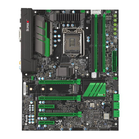
Supermicro C7Z170-OCE Motherboard User’s Manual 1-7 Power Supply As with all computer products, a stable power source is necessary for proper and reliable operation. It is even more important for processors that have high CPU clock rates. This motherboard accommodates 24-pin ATX power supplies. Although most power supplies generally meet the specifications required by the CPU, some are inadequate. - Page 21 Chapter 1: Introduction C7Z170-OCE Motherboard Image Note: All graphics shown in this manual were based upon the latest PCB Revision available at the time of publishing of the manual. The motherboard you've received may or may not look exactly the same...
- Page 22 Supermicro C7Z170-OCE Motherboard User’s Manual C7Z170-OCE Motherboard Layout C7Z170-OCE REV:1.00 DESIGNED IN USA FAN5 HD AUDIO HDMI/DP/SPDIF MH11 LAN2 LAN1 USB10(3.1) USB6/7(3.0) JPL2 JI2C2 JI2C1 JPL1 MH10 MH12 CPU Socket LGA1151 USB2/3 USB4/5 JSTBY1 USB11/12(3.1) CPU FAN DIMMA1 DIMMA2 JBT1...
- Page 23 Chapter 1: Introduction C7Z170-OCE Block Diagram SVID IMVP8 IMVP8 PCIe3.0_x16 PCIe3.0_x16 INTEL LGA1151 PCIe x16 SLOT #6 PLX8747 8.0GT/s 8.0GT/s DDR4 (CHA) DDI1 DDI 1 HDMI 1.4 DIMMA0 (Socket-H4) 2133/1866/1600MHz DIMMA1 DDI2 PCIe3.0_x16 DDI 2 Display Port 8.0GT/s DDR4 (CHB)
- Page 24 Supermicro C7Z170-OCE Motherboard User’s Manual C7Z170-OCE Quick Reference C7Z170-OCE REV:1.00 DESIGNED IN USA FAN5 HD AUDIO HDMI/DP/SPDIF MH11 LAN2 LAN1 USB10(3.1) USB6/7(3.0) JPL2 JI2C2 JI2C1 JPL1 MH10 MH12 CPU Socket LGA1151 USB2/3 USB4/5 JSTBY1 USB11/12(3.1) CPU FAN DIMMA1 DIMMA2 JBT1...
- Page 25 Chapter 1: Introduction Connector Description Audio FP Front Panel Audio Header Onboard Battery COM1 COM1 Port Header Digital Video Interface Fan 1,2,3,4,5 System/CPU Fan Headers (Fan1: CPU Fan) HD Audio High Definition Audio Connector HDMI/DP High Definition Multimedia Interface/DisplayPort I-SATA0~5 (Intel Z170) Serial ATA (SATA 3.0) Ports 0~5 (6Gb/sec) Speaker/buzzer (Pins 1~3: External Speaker, Pins 3~4: Buzzer) Front Panel Control Header...
- Page 26 Front Panel Accessible USB 3.1 Headers Description Color/State Status LED1 Onboard Standby PWR LED Green: Solid on Power On LED2 M.2 LED Green M.2 on board LED4 Status Display Digital Readout Download the status codes below* *Download the AMI status codes at https://www.supermicro.com.tw/manuals/other/AMI_BIOS_POST_ Codes_for_Grantley_Motherboards.pdf. 1-12...
-
Page 27: Chapter 2 Installation
Chapter 2: Installation Chapter 2 Installation 2-1 Installation Components and Tools Needed Screws Phillips-Head Screwdriver Intel LGA 1151 Processor DDR4 DIMMs PC Chassis Heatsink with Fan Power Supply Video Card (Optional) SATA/USB Optical Drive (Optional) SATA Hard Disk Drive... -
Page 28: Static-Sensitive Devices
Supermicro C7Z170-OCE Motherboard User’s Manual 2-2 Static-Sensitive Devices Electrostatic-Discharge (ESD) can damage electronic com ponents. To avoid damaging your system board, it is important to handle it very carefully. The following measures are generally sufficient to protect your equipment from ESD. -
Page 29: Processor And Heatsink Installation
CPU socket cap is in place and none of the socket pins are bent; otherwise, contact your retailer immediately. Refer to the Supermicro website for updates on CPU support. Installing the LGA1151 Processor 1. Press the load lever to release the load plate, which covers the CPU socket, from its locking position. - Page 30 Supermicro C7Z170-OCE Motherboard User’s Manual 2. Gently lift the load lever to open the load plate. Remove the plas- tic cap. 3. Use your thumb and your index finger to hold the CPU at the North center edge and the South center edge of the CPU.
- Page 31 Chapter 2: Installation 5. Do not rub the CPU against the surface or against any pins of the socket to avoid damaging the CPU or the socket. 6. With the CPU inside the socket, inspect the four corners of the CPU to make sure that the CPU is properly installed.
-
Page 32: Installing An Active Cpu Heatsink With Fan
Supermicro C7Z170-OCE Motherboard User’s Manual Installing an Active CPU Heatsink with Fan 1. Locate the CPU Fan power connector on the motherboard (Fan1: CPU Fan). 2. Position the heatsink so that the heatsink fan wires are clos- est to the CPU fan power con-... - Page 33 Chapter 2: Installation 7. Align the four heatsink fasteners with the mounting holes on the motherboard. Gently push the pairs of diagonal fasteners (#1 & #2, and #3 & #4) into the mounting holes until you hear a click. Also, make sure to orient each fastener so that the narrow end of the groove is pointing outward.
-
Page 34: Removing The Heatsink
Supermicro C7Z170-OCE Motherboard User’s Manual Removing the Heatsink Attention! We do not recommend that the CPU or the heatsink be removed. However, if you do need to remove the heatsink, please follow the instructions below to re- move the heatsink and to prevent damage done to the CPU or other components. -
Page 35: Installing Ddr4 Memory
Chapter 2: Installation 2-4 Installing DDR4 Memory Note: Check the Supermicro website for recommended memory modules. Attention! Exercise extreme care when installing or removing DIMM modules to prevent any possible damage. DIMM Installation C7Z170-OCE REV:1.00 DESIGNED IN USA FAN5 HD AUDIO HDMI/DP/SPDIF 1. -
Page 36: Memory Support
DIMMB2 (Green Slot) Towards the edge of the motherboard The C7Z170-OCE supports up to 64GB of Unbuffered (UDIMM) non-ECC DDR4 memory, up to 3000+MHz (OC) in four 288-pin memory slots. Populating these DIMM modules with a pair of memory modules of the same type and same size will result in interleaved memory, which will improve memory performance. -
Page 37: Memory Population Guidelines
Chapter 2: Installation Possible System Memory Allocation & Availability System Device Size Physical Memory Remaining (-Available) (4 GB Total System Memory) Firmware Hub flash memory (System BIOS) 1 MB 3.99 Local APIC 4 KB 3.99 Area Reserved for the chipset 2 MB 3.99 I/O APIC (4 Kbytes) -
Page 38: Motherboard Installation
Supermicro C7Z170-OCE Motherboard User’s Manual 2-5 Motherboard Installation All motherboards have standard mounting holes to fit different types of chassis. Make sure that the locations of all the mounting holes for both motherboard and chassis match. Although a chassis may have both plas- tic and metal mounting fasteners, metal ones are highly recommended because they ground the motherboard to the chassis. -
Page 39: Installing The Motherboard
Chapter 2: Installation Installing the Motherboard 1. Install the I/O shield into the back of the chassis. 2. Locate the mounting holes on the motherboard. (See the previous page.) 3. Locate the matching mounting holes on the chassis. Align the mounting holes on the motherboard against the mounting holes on the chassis. -
Page 40: Connectors/Io Ports
Supermicro C7Z170-OCE Motherboard User’s Manual 2-6 Connectors/IO Ports The I/O ports are color coded in conformance with the industry standards. See the figure below for the colors and locations of the various I/O ports. Back I/O Panel C7Z170-OCE REV:1.00 DESIGNED IN USA... -
Page 41: Universal Serial Bus (Usb)
G. USB 2.0 Header #4/5 StdA_SSRX+ Differential Pair H. USB 3.1 Header #11/12 GND_DRAIN Ground for Signal Return StdA_SSTX- SuperSpeed Transmitter I. USB 3.0 Header #8/9 StdA_SSTX+ Differential Pair C7Z170-OCE REV:1.00 DESIGNED IN USA FAN5 HD AUDIO HDMI/DP/SPDIF MH11 LAN1 LAN2 USB10(3.1) USB6/7(3.0) -
Page 42: Ethernet Port
Supermicro C7Z170-OCE Motherboard User’s Manual Ethernet Port LAN Ports Pin Definition Two Gigabit Ethernet ports (LAN1/LAN2) Pin# Definition Pin# Definition are located next to the DVI-D port on P2V5SB SGND the I/O back panel to provide network connections. These ports accept RJ45... -
Page 43: S/Pdif Port
Chapter 2: Installation S/PDIF Port A S/PDIF port is located next to the USB ports 0/1 on the I/O back panel. Use this port to connect to a compatible S/PDIF optical audio device. VESA® DisplayPort™ DisplayPort, developed by the VESA consortium, delivers digital display at a fast refresh rate. -
Page 44: Front Control Panel
JF1 contains header pins for various buttons and indicators that are normally located on a control panel at the front of the chassis. These connectors are designed specifically for use with Supermicro chassis. See the figure below for the descriptions of the front control panel buttons and LED indicators. -
Page 45: Front Control Panel Pin Definitions
Chapter 2: Installation Front Control Panel Pin Definitions Power LED Power LED Pin Definitions (JF1) The Power LED connection is located on Pin# Definition pins 15 and 16 of JF1. Refer to the table on the right for pin definitions. Ground HDD LED HDD LED... -
Page 46: Reset Button
Supermicro C7Z170-OCE Motherboard User’s Manual Reset Button Reset Button The Reset Button connection is located Pin Definitions (JF1) on pins 3 and 4 of JF1. Attach it to a Pin# Definition hardware reset switch on the computer Reset case to reset the system. Refer to the Ground table on the right for pin definitions. -
Page 47: Connecting Cables
+12V tor Pin Definitions +3.3V Pins Definition 1 through 4 Ground 5 through 8 +12V A. 24-Pin ATX Main PWR (Required) B. 8-Pin PWR C7Z170-OCE REV:1.00 DESIGNED IN USA FAN5 HD AUDIO HDMI/DP/SPDIF MH11 LAN2 LAN1 USB10(3.1) USB6/7(3.0) JPL2 JI2C2... -
Page 48: Fan Headers
Supermicro C7Z170-OCE Motherboard User’s Manual Fan Headers Fan Header Pin Definitions The C7Z170-OCE has five 4-pin fan head- Pin# Definition ers (Fan 1~Fan 5). Although pins 1-3 of Ground (Black) the fan headers are backward compatible 2.5A/+12V with the traditional 3-pin fans, we rec-... -
Page 49: Internal Buzzer
Pins 1~3 External Speaker use an external speaker, close pins 1~3 with a cable. See the table on the right for pin definitions. A. Internal Buzzer B. Speaker Header C7Z170-OCE REV:1.00 DESIGNED IN USA FAN5 HD AUDIO HDMI/DP/SPDIF MH11 LAN1 LAN2 USB10(3.1) -
Page 50: Onboard Power Led
Supermicro C7Z170-OCE Motherboard User’s Manual Onboard Power LED Onboard PWR LED Pin Definitions An onboard Power LED header is located Pin# Definition at JLED1. This Power LED header is con- nected to Front Control Panel located No Connection at JF1 to indicate the status of system Connection to PWR power. -
Page 51: Dom Pwr Connector
S/PDIF_Out The SPDIF Out (JSPDIF_OUT) is used for Ground digital audio output. You will also need the appropriate cable to use this feature. A. DOM PWR B. S/PDIF OUT C7Z170-OCE REV:1.00 DESIGNED IN USA FAN5 HD AUDIO HDMI/DP/SPDIF MH11 LAN1 LAN2 USB10(3.1) -
Page 52: Standby Power Header
Supermicro C7Z170-OCE Motherboard User’s Manual Standby Power Header Standby Power Pin Definitions The Standby Power header is located Pin# Definition at STBY1 on the motherboard. See the +5V Standby table on the right for pin definitions. Ground Wake-up M.2 Connector The PCI-E M.2 connector is for de-... -
Page 53: Front Panel Audio Header
Line_2_Right (not supplied). See the table on the right Ground for pin definitions for the header. Jack_Detect Line_2_Left Ground A. AUDIO FP C7Z170-OCE DESIGNED IN USA REV:1.00 FAN5 HD AUDIO HDMI/DP/SPDIF MH11 LAN2 LAN1 USB10(3.1) -
Page 54: Tpm Header
Supermicro C7Z170-OCE Motherboard User’s Manual TPM Header Trusted Platform Module Header Pin Definitions The JTPM1 header is used to con- Pin# Definition Pin# Definition nect a Trusted Platform Module LCLK (TPM), which is available from a LFRAME# No Pin third-party vendor. A TPM is a secu-... -
Page 55: Jumper Settings
LAN ports 1 and 2, respectively, Enabled (Default) on the motherboard. See the table on Disabled the right for jumper settings. The default setting is enabled. A. JPL1 B. JPL2 C7Z170-OCE REV:1.00 DESIGNED IN USA FAN5 HD AUDIO HDMI/DP/SPDIF MH11 LAN2 LAN1 USB10(3.1) -
Page 56: Clear Cmos & Jbt1
Supermicro C7Z170-OCE Motherboard User’s Manual Clear CMOS & JBT1 Clear CMOS (S11) and JBT1 are used to clear the saved system setup configuration stored in the CMOS chip. To clear the contents of the CMOS using JBT1, short the two pads of JBT1 with metallic conductor such as a flathead screwdriver. -
Page 57: Audio Enable
Normal (Default) feature of the motherboard. Slide the Recover switch from the default position to begin the recovery process. See Appendix D for details. A. Audio Enable B. BIOS Recovery C7Z170-OCE REV:1.00 DESIGNED IN USA FAN5 HD AUDIO HDMI/DP/SPDIF MH11 LAN2 LAN1 USB10(3.1) -
Page 58: Manufacturing Mode
Supermicro C7Z170-OCE Motherboard User’s Manual Manufacturing Mode Manufacturing Mode Jumper Settings Close Pin 2 and Pin 3 of jumper JPME2 Pin# Definition to bypass SPI flash security and force Normal (Default) the system to operate in Manufactur- Manufacture Mode ing Mode, allowing the user to flash the system firmware from a host server for system setting modifications. -
Page 59: Power Button (Power Button)
USB ports. It will then proceed to update the BIOS. Do NOT turn off the system when BIOS is updating. A. Power Button B. BIOS Restore C7Z170-OCE REV:1.00 DESIGNED IN USA FAN5 HD AUDIO HDMI/DP/SPDIF... -
Page 60: Onboard Indicators
Supermicro C7Z170-OCE Motherboard User’s Manual 2-9 Onboard Indicators LAN LEDs GLAN Activity Indicator One LAN port is located on the I/O back LED Settings panel of the motherboard. This Ethernet Color Status Definition LAN port has two LEDs (Light Emitting... -
Page 61: Status Display
Status Definition connected to the M.2 slot. See No Device Connected the table on the right for more M.2 On Board information. A. Status Display B. M.2 LED C7Z170-OCE REV:1.00 DESIGNED IN USA FAN5 HD AUDIO HDMI/DP/SPDIF MH11 LAN2 LAN1 USB10(3.1) -
Page 62: Sata Connections
Supermicro C7Z170-OCE Motherboard User’s Manual 2-10 SATA Connections SATA Connections (I-SATA0~I-SATA5) Six Serial ATA (SATA) 3.0 connectors (I-SATA 0~5) are supported on the board. These I-SATA 3.0 ports are supported by the Intel Z170 PCH chip (supports RAID 0,1,5,10). See the table below for pin definitions. -
Page 63: Chapter 3 Troubleshooting
Chapter 3: Troubleshooting Chapter 3 Troubleshooting 3-1 Troubleshooting Procedures Use the following procedures to troubleshoot your system. If you have followed all of the procedures below and still need assistance, refer to the ‘Technical Support Procedures’ and/or ‘Returning Merchandise for Service’ section(s) in this chapter. -
Page 64: Memory Errors
Supermicro C7Z170-OCE Motherboard User’s Manual 5. The battery on your motherboard may be old. Check to make sure that it still supplies ~3VDC. If it does not, replace it with a new one. No Video 1. If the power is on, but you have no video--in this case, you will need to remove all the add-on cards and cables first. -
Page 65: Technical Support Procedures
Before contacting Technical Support, please make sure that you have followed all the steps listed below. Also, note that as a motherboard manufacturer, Supermicro does not sell directly to end users, so it is best to first check with your distributor or reseller for troubleshooting services. -
Page 66: Frequently Asked Questions
Supermicro C7Z170-OCE Motherboard User’s Manual 3-3 Frequently Asked Questions Question: What type of memory does my motherboard support? Answer: The C7ZZ170-OCE supports up to 64GB of unbuffered Non-ECC DDR4. See Section 2-4 for details on installing memory. Question: How do I update my BIOS? Answer: We do NOT recommend that you upgrade your BIOS if you are not experiencing any problems with your system. -
Page 67: Battery Removal And Installation
Chapter 3: Troubleshooting Question: I think my BIOS is corrupted. How can I recover my BIOS? Answer: Please see Appendix C-BIOS Recovery for detailed instructions. 3-4 Battery Removal and Installation Battery Removal To remove the onboard battery, follow the steps below: 1. -
Page 68: Battery Installation
Supermicro C7Z170-OCE Motherboard User’s Manual Battery Installation 1. To install an onboard battery, follow the steps 1 & 2 above and continue below: 2. Identify the battery's polarity. The positive (+) side should be fac- ing up. 3. Insert the battery into the battery holder and push it down until you hear a click to ensure that the battery is securely locked. -
Page 69: Chapter 4 Bios
BIOS 4-1 Introduction This chapter describes the AMI BIOS setup utility for the C7Z170-OCE. The ROM BIOS is stored in a Flash EEPROM and can be easily updated. This chapter describes the basic navigation of the AMI BIOS setup utility setup screens. -
Page 70: How To Change The Configuration Data
Supermicro C7Z170-OCE Motherboard User’s Manual The AMI BIOS GUI setup utility uses a mouse pointer navigation system similar to standard graphical user interfaces. Hover and click an icon to select a section, click a down arrow to select from an options list. -
Page 71: System Information
4-2 System Information The System Information Panel displays the motherboard's configuration. The following information among others is displayed in this section: • Motherboard Model Name - C7Z170-OCE. • BIOS Version - this item displays the BIOS version number. • Build Date and Time - displays the BIOS build date and time. -
Page 72: Cpu
Supermicro C7Z170-OCE Motherboard User’s Manual 4-3 CPU The following information is displayed in this section: • Name - indicates the model name of the CPU. • Type - indicates the brand, model name, model number of the CPU and it's rated clock speed. -
Page 73: Cpu Configuration
Chapter 4: AMI BIOS CPU Configuration Set all options for the processor in this section. The following CPU information will be displayed: • CPU Type - displays the CPU type. • Type - indicates the brand, model name, model number of the CPU and it's rated clock speed. -
Page 74: Hardware Prefetcher
Supermicro C7Z170-OCE Motherboard User’s Manual C6DRAM Select Enabled to allow moving of DRAM contents to PRM memory when CPU is in C6 state. The options are Disabled and Enabled. SW Guard Extension (SGX) Select Enabled to activate the Software Guard Extensions (SGX). The options are Software Controlled, Enabled, and Disabled. - Page 75 Chapter 4: AMI BIOS Hyper-Threading Select Enabled to support Intel Hyper-threading Technology to enhance CPU performance. The options are Disabled and Enabled. BIST Select Enabled to activate the Built-In Self Test (BIST) on reset. The options are Disabled and Enabled. JTAG C10 Power Select Enabled to activate power JTAG in C10 and deeper power states.
-
Page 76: Debug Interface
Supermicro C7Z170-OCE Motherboard User’s Manual Alias Check Request Use this feature to set up Alias Check Request. The options are Enabled and Disabled. DPR Memory Size Use this feature to set the DMA Protected Range (DPR) memory size. Select a value. -
Page 77: Power And Performance
Chapter 4: AMI BIOS Voltage Optimization Select Enable to activate Voltage Optimization. The options are Disabled and Enabled. Power and Performance CPU - Power Management Control Boot performance mode This option enables the selection of the default CPU performance during system boot. -
Page 78: View/Configure Turbo Options
Supermicro C7Z170-OCE Motherboard User’s Manual View/Configure Turbo Options The following information is displayed in this section: • Max Turbo Power Limit • Min Turbo Power Limit • Package TDP Limit • Power Limit 1 • Power Limit 2 • 1-core Turbo Ratio •... -
Page 79: Cpu Vr Settings
Chapter 4: AMI BIOS Energy Efficient Turbo Select Enabled to activate Energy Efficient Turbo. This feature will op- portunistically lower the turbo frequency to increase efficiency. We recommend to leave this enabled and disable only in overclocking situa- tions where the turbo frequency must remain constant. The options are Disabled and Enabled. -
Page 80: Acoustic Noise Settings
Supermicro C7Z170-OCE Motherboard User’s Manual Acoustic Noise Settings Acoustic Noise Mitigation Select Enable to help mitigate acoustic noise on certain SKUs when the CPU is in deeper C-State. The options are Disabled and Enabled. When the above is set to Enabled, the followings can be configured:... -
Page 81: Core/Ia Vr Settings
Chapter 4: AMI BIOS Slow Slew Rate for IA Domain This feature sets the VR SA Slew Rate for Deep Package C-State ramp time. Slow slew rate equals Fast divided by the number 2, 4, 8, or 16. This feature is used to help reduce acoustic noise. The options are Fast/2, Fast/4, Fast/8, and Fast/16. - Page 82 Supermicro C7Z170-OCE Motherboard User’s Manual PS3 Enable Enable or Disables PS3. Uses BIOS VR mailbox command line 0x3. The options are Disabled and Enabled. PS4 Enable Enable or Disables PS4. Uses BIOS VR mailbox command line 0x3. The options are Disabled and Enabled.
-
Page 83: Gt-Sliced Vr Settings
Chapter 4: AMI BIOS TDC Time Window The TDC Time Window is defined in milliseconds. Valid range is 1-8ms and 10ms. Note that 9ms has no valid encoding in the MSR definition. The options are 1ms, 2ms, 3ms, 4ms, 5ms, 6ms, 7ms, 8ms, and 10ms. - Page 84 Supermicro C7Z170-OCE Motherboard User’s Manual PS Current Threshold3 The PS Current Threshold2 is defined in 1/4A (Amperes) increments and uses the BIOS mailbox command 0x3. A value of 400 equals 100A. Range is 0-512 which translates to 0-128A. Enter 0 for AUTO.
- Page 85 Chapter 4: AMI BIOS TDC Current Limit The TDC Current Limit is defined in 1/8A (Amperes) increments and uses the BIOS mailbox command 0x1A. A value of 1000 equals 125A. Valid range is 0-32767. Enter 0 for 0 Amps. TDC Time Window The TDC Time Window is defined in milliseconds.
-
Page 86: C3 Latency Control (Msr 0X60A)
Supermicro C7Z170-OCE Motherboard User’s Manual CState Pre-Wake When set, this option enables or disables the C-State pre wake. The op- tions are Disabled and Enabled. IO MWAIT Redirection When enabled, this feature will map and send the IO read instructions to the IO registers. -
Page 87: Custom P-State Table
Chapter 4: AMI BIOS Latency Use this item to set the C6/C7 long latency time value. Valid range is 0-1023. The default setting is 118. Thermal Monitor Use this feature to enable the thermal monitor support. The options are Disabled and Enabled. Timed MWAIT Use this feature to enable the Timed MWAIT support. -
Page 88: Gt-Power Management
Supermicro C7Z170-OCE Motherboard User’s Manual GT-Power Management RC6 (Render Standby) Use this feature to enable Render Standby support. The options are Enabled and Disabled. Maximum GT Frequency This option is the Maximum GT Frequency as defined by the user. Choose between 300MHz (RPN) and 1200MHz (RP0). Any value beyond this range will be clipped to its min/max supported by the CPU. -
Page 89: Cpu Overclocking
Chapter 4: AMI BIOS CPU OverClocking BCLK Clock Frequency (1/100 MHz) Use this item to set the CPU clock override value for the host system. The default setting is 10000. FCLK Frequency for Early Power On Select the FCLK frequency for early power on. The options are Normal (800MHz), 1GHz, and 400MHz. - Page 90 Supermicro C7Z170-OCE Motherboard User’s Manual 2-Core Ratio Limit Override This increases (multiplies) 2 clock speeds in the CPU core in relation to the bus speed when two CPU cores are active. Enter 0 to use the manufacturer's default setting. 3-Core Ratio Limit Override This increases (multiplies) 3 clock speeds in the CPU core in relation to the bus speed when three CPU cores are active.
- Page 91 Chapter 4: AMI BIOS Turbo Mode This feature allows processor cores to run faster than the rated operating frequency in specific conditions. The options are Disabled and Enabled. If this feature is set to Enabled, the following items will be displayed: Package Power Limit MSR Lock This feature enables or disables the locking of Package Power Limit settings.
- Page 92 Supermicro C7Z170-OCE Motherboard User’s Manual Power Limit 1 Time Window This item determines how long the time window over which the TDP value is maintained. Use the number keys on your keyboard to enter the value. The default setting is 8. This value may vary between 0~128.
- Page 93 Chapter 4: AMI BIOS CPU Flex Ratio Override Select Enabled to activate CPU Flex Ratio programming. The options are Enabled and Disabled. CPU Flex Ratio Settings When CPU Flex Ratio Override is enabled, this sets the value for the CPU Flex Ratio. The default is 16. Core Max OC Ratio This option sets the maximum overclocking ratio for the CPU core.
- Page 94 Supermicro C7Z170-OCE Motherboard User’s Manual Ring Min OC Ratio This option sets the minimum overclocking ratio for the RING domain. Press "+" or "-" on your keyboard to change the value. Uncore Voltage Offset Use this feature to set the uncore domain Voltage Offset value from -1000mV to +1000mV.
-
Page 95: Acoustic Noise Settings
Chapter 4: AMI BIOS PSYS Slope PSYS Slope is defined in 1/100 increments and uses the BIOS VR mailbox command 0x9. Valid range is 0-200. For example, enter 125 for a 1.25 slope. Enter 0 for AUTO. PSYS Offset PSYS Offset is defined in 1/4 increments and uses the BIOS VR mailbox command 0x9. -
Page 96: Core/Ia Vr Settings
Supermicro C7Z170-OCE Motherboard User’s Manual Slow Slew Rate for GT Domain This feature sets the VR GT Slew Rate for Deep Package C-State ramp time. Slow slew rate equals Fast divided by the number 2, 4, 8, or 16. This feature is used to help reduce acoustic noise. The options are Fast/2, Fast/4, Fast/8, and Fast/16. - Page 97 Chapter 4: AMI BIOS PS Current Threshold2 The PS Current Threshold2 is defined in 1/4A (Amperes) increments and uses the BIOS mailbox command 0x3. A value of 400 equals 100A. Valid range is 0-512 which translates to 0-128A. Enter 0 for AUTO. Default is 20 for 5A.
- Page 98 Supermicro C7Z170-OCE Motherboard User’s Manual VR Voltage Limit This feature sets the Voltage Regulator voltage limit. The value is represented in mV. A value of 1250 equals 1.25V. Set this number to 0 for Auto. This uses the BIOS VR mailbox command 0x6.
-
Page 99: Memory
Chapter 4: AMI BIOS 4-4 Memory The following information is displayed in this section: • Memory RC Version • Memory Frequency • Memory Timings (tCL-tRCD-tRP-tRAS) • DIMM#A1, DIMM#A2, DIMM#B1, DIMM#B2 Maximum Memory Frequency This option selects the type/speed of the memory installed. The options are 1333, 1600, 1867, 2133, 2400, 2667, 2933, and 3200. -
Page 100: Memory Overclocking
Supermicro C7Z170-OCE Motherboard User’s Manual Channel A DIMM Control This feature enables or disables the selected Channel A DIMM slot(s). The settings are Enable Both DIMMs, Disable DIMM0, Disable DIMM1, and Disable Both DIMMs. Channel B DIMM Control This feature enables or disables the selected Channel B DIMM slot(s). - Page 101 Chapter 4: AMI BIOS • tRFC • tRRD • tRTP • • tWTR • NMode • VDD [mV] Memory Profile Use this feature to set Performance Memory Profiles which may cause impact on memory behavior. The options are Default Profile, Custom profile, and XMP profile 1.
- Page 102 Supermicro C7Z170-OCE Motherboard User’s Manual Memory Voltage This option selects the Memory Voltage The options are Default, 1.20V, 1.25V, 1.30V, 1.35V, 1.40V, 1.45V, 1.50V, 1.55V, 1.60V, 1.65V, 1.70V, and 1.75V. This option configures the Cas Latency Range. Enter a number between 4-18.
-
Page 103: 3Rd Timing
Chapter 4: AMI BIOS This option configures the Minimum Write Recovery Time. Enter a number between 1-38. The options are Auto, 5, 6, 7, 8, 10, 12, 14, 16, 18, 20, and 24. tWTR This option configures the Minimum Internal Write to Read Com- mand Delay Time. - Page 104 Supermicro C7Z170-OCE Motherboard User’s Manual ODT_read_duration This option configures the ODT Read Duration. Enter a numeric value. The default is 0. ODT_Read_Delay This option configures the ODT Read Delay. Enter a numeric value. The default is 0. ODT_write_duration This option configures the ODT Write Duration. Enter a numeric value.
- Page 105 Chapter 4: AMI BIOS tRDRD_dd This option configures the between module read to read delay (tRDRD_dd). Enter a numeric value. The default is 7. tRDWR_sg This option configures the between module read to write delay (tRDWR_sg). Enter a numeric value. The default is 9. tRDWR_dg This option configures the between module read to write delay (tRDWR_dg).
- Page 106 Supermicro C7Z170-OCE Motherboard User’s Manual tRWRW_dg This option configures the between module read to write delay (tWRWR_dg). Enter a numeric value. The default is 4. tRWRW_dr This option configures the between module read to write delay (tWRWR_dr). Enter a numeric value. The default is 7.
-
Page 107: Advanced
Chapter 4: AMI BIOS DIIBwEn[2] This option configures DIIBwEn[2]. Enter a numeric value. The default is 2. DIIBwEn[3] This option configures DIIBwEn[3]. Enter a numeric value. The default is 2. 4-5 Advanced Boot Feature Quiet Boot Use this feature to select the screen display between the POST messages and the OEM logo upon bootup. - Page 108 Supermicro C7Z170-OCE Motherboard User’s Manual Wait for "F1" Error Use this feature to force the system to wait until the 'F1' key is pressed an error occurs. The options are Disabled and Enabled. Re-try Boot If this item is enabled, the BIOS will automatically reboot the system from a specified boot device after its initial boot failure.
- Page 109 Chapter 4: AMI BIOS NCT6792D Super IO Configuration SuperIO Chip NCT6792D Serial Port 1 Configuration Serial Port This item will Enable or Disable Serial Port 1 (COM1). Place a tick mark on the box to enable Serial Port 1. The default is Enabled. Device Settings This item displays the current IRQ setting for Serial Port 1 (COM1).
-
Page 110: Serial Port Console Redirection
Supermicro C7Z170-OCE Motherboard User’s Manual Serial Port Console Redirection COM 0 Console Redirection Select Enabled to enable COM Port 1 Console Redirection, which will al- low a client machine to be connected to a host machine at a remote site for networking. - Page 111 Chapter 4: AMI BIOS Bits Per second Use this item to set the transmission speed for a serial port used in Console Redirection. Make sure that the same speed is used in the host computer and the client computer. A lower transmission speed may be required for long and busy lines.
- Page 112 Supermicro C7Z170-OCE Motherboard User’s Manual Resolution 100x31 Select Enabled for extended-terminal resolution support. The options are Enabled (checked) and Disabled (unchecked). Legacy OS Redirection Resolution Use this item to select the number of rows and columns used in Console Redirection for legacy OS support. The options are 80x24 and 80x25.
- Page 113 Chapter 4: AMI BIOS Console Redirection Settings Out-of-Band Mgmt Port The feature selects a serial port in a client server to be used by the Windows Emergency Management Services (EMS) to communicate with a remote host server. The options are dependent on the avail- able COM ports.
-
Page 114: System Agent (Sa) Configuration
Supermicro C7Z170-OCE Motherboard User’s Manual System Agent (SA) Configuration The following information will be displayed: • SA PCIe Code Version • VT-d Capability PEG ASPM This feature configures the ASPM (Active State Power Management) settings for the graphics devices installed on PCI-E Slot 0, Slot 1, or Slot2. -
Page 115: Graphics Configuration
Chapter 4: AMI BIOS Graphics Configuration Graphics Turbo IMON Current Use this feature to set the limit on the current voltage regulator. Valid range is 14-31. Default is 31. Skip Scanning of External Gfx Card Use this feature to scan for External Gfx Card on PEG and PCH PCIE Ports. If this feature is enabled, the system will not scan for a new card. -
Page 116: Internal Graphics
Supermicro C7Z170-OCE Motherboard User’s Manual Primary PCIE This feature allows the user to specy which graphics card to be used as the primary graphics card. The options are Auto, PCIE1, PCIE2, PCIE3, PCIE4, PCIE5, PCIE6, PCIE7, PCIE8, PCIE9, PCIE10, PCIE11, PCIE12, PCIE13, PCIE14, PCIE15, PCIE16, PCIE17, PCIE18, and PCIE19. -
Page 117: Graphics Overclocking
Chapter 4: AMI BIOS Algorithm Select either One-Time or Periodic for HDCP re-encryption flow. PM Support Activating this feature will enable Power Management BIOS support. The options are Enabled and Disabled. PAVP Enable Use the feature to enable Protect Audio Video Path Mode. The options are Enabled and Disabled. -
Page 118: Gt-Sliced Vr Settings
Supermicro C7Z170-OCE Motherboard User’s Manual Offset Prefix Use this feature to set the Offset value as a positive (+) number or a negative (-) number. The default setting is "+". GT Unslice Domain GT OverClocking Frequency This option selects the Overclocked RPO frequency in multiples of 50MHz. - Page 119 Chapter 4: AMI BIOS DC Loadline DC Loadline is defined in 1/100 mOhms and uses the BIOS mailbox command 0x2. A value of 100 equals 1.0 mOhm, and 1255 is 12.55 mOhms. Valid range is 0-6249 (0-62.49 mOhms). Enter 0 for AUTO. PS Current Threshold1 The PS Current Threshold1 is defined in 1/4A (Amperes) increments and uses the BIOS mailbox command 0x3.
- Page 120 Supermicro C7Z170-OCE Motherboard User’s Manual IMON Prefix This feature sets the IMON offset value to a positive or negative num- ber. The options are + and -. VR Current Limit This feature sets the Voltage Regulator current limit. The value repre- sents the maximum instantaneous current allowed at any given time.
- Page 121 Chapter 4: AMI BIOS PCH-IO Configuration PCI Express Configuration DMI Link ASPM Control Use this feature to set the ASPM (Active State Power Management) state on the SA (System Agent) side of the DMI Link. The options are Disabled and Enabled. PCH SLOT3 PCI-E 3.0 X1 (IN X4) PCI Express Root Port 3 Select Enabled to activate PCI Express Root Port 3.
- Page 122 Supermicro C7Z170-OCE Motherboard User’s Manual L1 Substates Select to configure the L1 Substates. The options are Disabled, L1.1, L1.2, and L1.1 & L1.2. PCIe Speed Set this option to configure the speed setting of this PCIE slot . The options are Auto, Gen1, Gen2, and Gen3.
- Page 123 Chapter 4: AMI BIOS ASPM This feature configures the ASPM (Active State Power Management) settings for the graphics devices installed on PCI-E Slot 0, Slot 1, or Slot2. The options are Disabled, L0s, L1, L0sL1, and Auto. L1 Substates Select to configure the L1 Substates. The options are Disabled, L1.1, L1.2, and L1.1 &...
-
Page 124: Sata And Rst Configuration
Supermicro C7Z170-OCE Motherboard User’s Manual SATA and RST Configuration SATA Controller(s) Select Disabled to disable the onboard SATA Controllers. The options are Enabled and Disabled. SATA Mode Selection This item selects the mode for the installed SATA drives. The options are AHCI and RAID. -
Page 125: Pch Fw Configuration
Chapter 4: AMI BIOS a SATA disk drive without shutting down the system. The options are Disabled and Enabled. Configured as eSATA This item displays the eSATA status for the detected hard drive. Spin Up Device When this option is disabled, all drives will spin up at boot. When this option is enabled, it will perform Staggered Spin Up on any drive this option is activated. -
Page 126: Usb Configuration
Supermicro C7Z170-OCE Motherboard User’s Manual USB Configuration The following information for USB Configuration is displayed. • USB Module Version • USB Controllers • USB Devices Legacy USB Support Select Enabled to support legacy USB devices. Select Auto to disable legacy support when legacy USB devices are not present. If Disable is selected, legacy USB devices will not be supported. -
Page 127: Pcie/Pci/Pnp Configuration
Chapter 4: AMI BIOS Install Windows 7 USB Support Enable this feature to use the USB keyboard and mouse during the Windows 7 installation, since the native XHCI driver support is unavailable. Use a SATA optical drive as a USB drive, and USB CD/ DVD drives are not supported. -
Page 128: Network Stack
Supermicro C7Z170-OCE Motherboard User’s Manual PCIe/PCI/PnP Configuration PCI/PCIX/PCIe Slot1 OPROM, PCI/PCIX/PCIe Slot2 OPROM, PCI/PCIX/PCIe Slot3 OPROM, PCI/PCIX/PCIe Slot4 OPROM, PCI/PCIX/PCIe Slot5 OPROM Select Disabled to deactivate the selected slot, Legacy to activate the slot in legacy mode and EFI to activate the slot in EFI mode. The op- tions are Disabled, Legacy, and EFI. -
Page 129: Security
Chapter 4: AMI BIOS Security This menu allows the user to configure the following security settings for the system. • If the Administrator password is defined ONLY - this controls access to the BIOS setup ONLY. • If the User's password is defined ONLY - this password will need to be entered upon each system boot, and will also have Administrator rights in the setup. -
Page 130: Secure Boot
Supermicro C7Z170-OCE Motherboard User’s Manual Secure Boot The following items will be displayed: • System Mode • Secure Boot • Vendor Keys Attempt Secure Boot Select Enabled for Secure Boot flow control. This feature is available when the platform key (PK) is pre-registered, the platform operates in the user mode, and CSM is disabled in the Setup utility. -
Page 131: Key Management
Chapter 4: AMI BIOS Key Management Provision Factory Default Keys Allow provisioning the factory default secure boot keys when system is in setup mode. The options are Disabled and Enabled. (Available when Secure Boot Mode is set to 'Customized') Key Management allows experienced users to modify Secure Boot Vari- ables. -
Page 132: Authorized Signatures
Supermicro C7Z170-OCE Motherboard User’s Manual Platform Key (PK) This item uploads and installs a secure Platform Key. You may insert a factory default key or load from a file. The file formats accepted are: 1) Public Key Certificate a. EFI Signature List b. - Page 133 Chapter 4: AMI BIOS 2) EFI Time Based Authenticated Variable When prompted, select "Yes" to load Factory Defaults or "No' to load from a file. Authorized TimeStamps This item uploads and installs an Authorized Time Stamp . You may insert a factory default key or load from a file.
-
Page 134: Thermal
Supermicro C7Z170-OCE Motherboard User’s Manual 4-6 Thermal System Temperature Fan Speed Control Mode This feature allows the user to decide how the system controls the speeds of the onboard fans. The CPU temperature and the fan speed are correlative. When the CPU on-die temperature increases, the fan speed will also increase for effective system cooling. - Page 135 Chapter 4: AMI BIOS • Peripheral Temperature - displays the detected peripheral de- vice temperature. • PCH Temperature - indicates the detected PCH chip temperature. System Health The following items will be displayed (Voltage): • VCPU • • VCPU_SA • 5VCC •...
-
Page 136: Save & Exit
Supermicro C7Z170-OCE Motherboard User’s Manual 4-7 Save & Exit Boot mode select Use this item to select the type of device to be used for system boot. The options are Legacy, UEFI, and Dual. FIXED BOOT ORDER Priorities This option prioritizes the order of bootable devices from which the system will boot. -
Page 137: Iba Cl Slot 00Fe V0110
Chapter 4: AMI BIOS IBA CL Slot 00FE v0110 Launch EFI Shell from filesystem device This option will attempt to launch the EFI Shell application (shell.efi) from one of the available file system devices. Select OK to activate, otherwise, click Cancel. For the following options, select OK to initiate, otherwise, click Cancel. -
Page 138: Bios Update
Supermicro C7Z170-OCE Motherboard User’s Manual 4-8 BIOS Update The following items will be displayed: • BIOS Version • BIOS Tag. • Date • Time Start Update Use this utility to prepare BIOS Update with ME. 1. Click "Start Update" enter the SuperFlash utility. - Page 139 Chapter 4: AMI BIOS 6. Select "Start Flash" to flash the BIOS. A pop-up message will ap- pear to show the progress of the BIOS flash. 7. If the flash is successful, a pop-up message will indicate the result. Select "OK" to complete the BIOS flash and to reboot the system. Go to the "SYSTEM INFORMATION - Motherboard"...
- Page 140 Supermicro C7Z170-OCE Motherboard User’s Manual Notes 4-72...
-
Page 141: Appendix A Bios Error Beep Codes
Appendix A: POST Error Beep Codes Appendix A BIOS Error Beep Codes During the POST (Power-On Self-Test) routines, which are performed each time the system is powered on, errors may occur. Non-fatal errors are those which, in most cases, allow the system to continue with bootup. - Page 142 Supermicro C7Z170-OCE Motherboard User’s Manual Notes...
-
Page 143: Appendix B Software Installation Instructions
(Note: To install the Windows Operating System, please refer to the instructions posted on our website at http://www.supermicro.com/support/manuals/.) Driver/Tool Installation Display Screen Note 1. Click the icons showing a hand writing on the paper to view the readme files for each item. -
Page 144: Configuring Superdoctor ® V
Supermicro C7Z170-OCE Motherboard User’s Manual ® B-2 Configuring SuperDoctor The SuperDoctor 5 program is a Web-based management tool that supports remote management capability. It includes Remote and Local Management tools. The local management tool is called the SD 5 Client. - Page 145 Appendix B: Software Installation Instructions Note: The SuperDoctor 5 software and manual may be downloaded from our website at: https://www.supermicro.com/Products/nfo/SMS_SD5.cfm...
- Page 146 Supermicro C7Z170-OCE Motherboard User’s Manual Notes...
-
Page 147: Appendix C Uefi Bios Recovery Instructions
Attention! Do not upgrade the BIOS unless your system has a BIOS-related issue. Flashing the wrong BIOS can cause irreparable damage to the system. In no event shall Supermicro be liable for direct, indirect, special, incidental, or consequential damages aris- ing from a BIOS update. -
Page 148: To Recover The Main Bios Block Using A Usb-Attached Device
Root "\" Directory of a USB device or a writeable CD/DVD. Note: If you cannot locate the "SUPER.ROM" file in your driver disk, visit our website at www.supermicro.com to download the BIOS image into a USB flash device (save in the root folder) and rename it "SUPER.ROM"... - Page 149 Appendix C: UEFI BIOS Recovery 4. After locating the new BIOS binary image, the system will enter the BIOS Recovery menu as shown below. Note: At this point, you may decide if you want to start with BIOS Recovery. If you decide to proceed with BIOS Recovery, follow the procedures below.
- Page 150 Supermicro C7Z170-OCE Motherboard User’s Manual Notes...
-
Page 151: Appendix D Dual Boot Block
Appendix D: Dual Boot Block Appendix D Dual Boot Block D-1 Introduction This motherboard supports the Dual Boot Block feature, which is the last- ditch mechanism to recover the BIOS boot block. This section provides an introduction to the feature. BIOS Boot Block A BIOS boot block is the minimum BIOS loader required to enable nec- essary hardware components for the BIOS crisis recovery flash that will... -
Page 152: D-2 Steps To Reboot The System By Switch Jbr1
Supermicro C7Z170-OCE Motherboard User’s Manual D-2 Steps to Reboot the System by switch JBR1 1. Power down the system. 2. On switch JBR1 slide switch to ON, and power on the system. 3. Follow the BIOS recovery SOP listed in the previous chapter (Appendix C). - Page 153 (Disclaimer Continued) The products sold by Supermicro are not intended for and will not be used in life support systems, medical equipment, nuclear facilities or systems, aircraft, aircraft devices, aircraft/emergency com- munication devices or other critical systems whose failure to perform be reasonably expected to result in significant injury or loss of life or catastrophic property damage.
Need help?
Do you have a question about the C7Z170-OCE and is the answer not in the manual?
Questions and answers