Advertisement
Advertisement
Table of Contents

Related Manuals for peerless-AV LCW420A


Summary of Contents for peerless-AV LCW420A
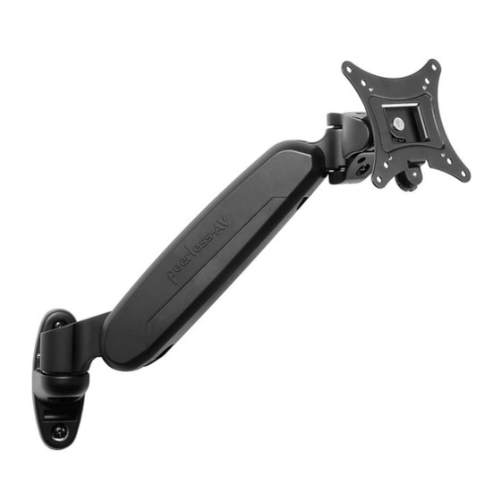
- Page 1 Installation and Assembly: Wall Mount for 19" - 30" LCD Screens Models: LCW420A, LCW620A LCW420A LCW620A Max Load Capacity: 15 lbs (6.8 kg) 2300 White Oak Circle • Aurora, Il 60502 • (800) 865-2112 • Fax: (800) 359-6500 • www.peerlessmounts.com...
- Page 2 NOTE: Read entire instruction sheet before you start installation and assembly. WARNING • Do not begin to install your Peerless product until you have read and understood the instructions and warnings contained in this Installation Sheet. If you have any questions regarding any of the instructions or warnings, please call Peerless customer care at 1-800-865-2112.
-
Page 3: Parts List
Before you begin, make sure all parts shown are included with your product. Parts List LCW420A LCW620A Description A wall plate B single link arm assembly double link arm assembly C wood screw D M6 washer E concrete anchor F M4 x 12 mm phillips screw... -
Page 4: Installation To Wood Stud Wall
Installation to Wood Stud Wall WARNING • Installer must verify that the supporting surface will safely support the combined load of the equipment and all attached hardware and components. • Tighten wood screws so that wall plate is fi rmly attached, but do not overtighten. Overtightening can damage the screws, greatly reducing their holding power. -
Page 5: Installation To Solid Concrete Or Cinder Block
Installation to Solid Concrete and Cinder Block WARNING • When installing Peerless wall mounts on cinder block, verify that you have a minimum of 1-3/8" (35mm) of actual concrete thickness in the hole to be used for the concrete anchors. Do not drill into mortar joints! Be sure to mount in a solid part of the block, generally 1"... -
Page 6: Attaching Arm Assembly To Screen
Attaching Adapter Plate to Screen WARNING • Tighten screws so adapter plate is fi rmly attached. Do not tighten with excessive force. Overtightening can cause stress damage to screws, greatly reducing their holding power and possibly causing screw heads to become detached. - Page 7 Insert arm assembly (B) onto wall plate (A) as shown in fi gure 3.1. Tighten set screw on rear of arm assembly (B) using 2.5mm allen wrench (J) as shown in fi gure 3.2. fi g. 3.1 fi g. 3.2 SET SCREW Secure arm assembly (B) to wall plate (A) with Hook adapter plate onto arm assembly (B).
- Page 8 Cables may be routed using cavity in arm assembly (B). Remove the cable cover on arm assembly (B) by pressing fi rmly in the middle of the cable cover and then pulling the fl anges of the cable cover. Route the cables in arm assembly (B) and then reinstall the cable cover.
- Page 9 To lock down rotation, tighten set screw shown in detail 2. To lock down tilt, tighten screw shown in detail 3. To lock down swivel, tighten screw shown in detail 4. To lock down height adjustment, tighten set screw shown in detail 5. TILT SCREW SET SCREW 360°...
- Page 10 Limited Warranty or impose any obligation on Peerless in connection with the sale of any Peerless® product. This warranty gives specifi c legal rights, and you may also have other rights which vary from state to state. www.peerless-av.com © 2012 Peerless Industries, Inc.
Need help?
Do you have a question about the LCW420A and is the answer not in the manual?
Questions and answers