Advertisement
Installation and Assembly:
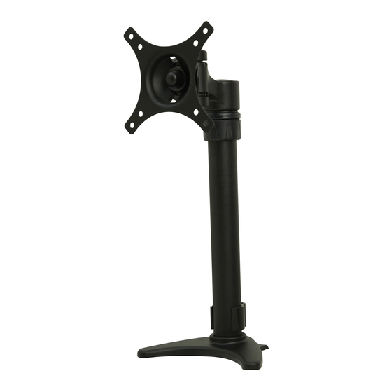
Desktop Mount with Desk Clamp and Grommet for 19" - 30"
LCD Screens
Models: LCT100S
GROMMET INSTALLATION
DESK CLAMP INSTALLATION
Max Load Capacity: 20 lbs (9 kg)
2300 White Oak Circle • Aurora, Il 60502 • (800) 865-2112 • Fax: (800) 359-6500 • www.peerless-av.com
ISSUED: 07-25-11 SHEET #: 090-9202-5 07-16-13
Advertisement
Table of Contents

Subscribe to Our Youtube Channel
Related Manuals for peerless-AV LCT100S


Summary of Contents for peerless-AV LCT100S
- Page 1 Desktop Mount with Desk Clamp and Grommet for 19" - 30" LCD Screens Models: LCT100S GROMMET INSTALLATION DESK CLAMP INSTALLATION Max Load Capacity: 20 lbs (9 kg) 2300 White Oak Circle • Aurora, Il 60502 • (800) 865-2112 • Fax: (800) 359-6500 • www.peerless-av.com ISSUED: 07-25-11 SHEET #: 090-9202-5 07-16-13...
- Page 2 NOTE: Read entire instruction sheet before you start installation and assembly. WARNING • Do not begin to install your Peerless product until you have read and understood the instructions and warnings contained in this Installation Sheet. If you have any questions regarding any of the instructions or warnings, please call Peerless customer care at 1-800-865-2112.
- Page 3 Before you begin, make sure all parts shown are included with your product. Parts List Description column assembly adapter plate assembly grommet assembly round rubber pads square rubber pads M4 x 12 mm phillips screw M4 x 25 mm phillips screw spacer 4 mm allen wrench 2.5 mm allen wrench...
- Page 4 Clamp Installation Method Grommet Installation Method Remove clamp assembly from column assembly Apply four rubber pads (D, E) to bottom of column (A) as shown in fi gure 1.1. Remove mounting plate assembly (A) as shown below. Attach column from grommet assembly (C) and attach to column assembly (A) to mounting surface with a maximum assembly (A) with four M6 x 8 mm screws using thickness of 3".
- Page 5 Attaching Adapter Plate Assembly to Screen WARNING • Tighten screws so adapter plate assembly is fi rmly attached. Do not tighten with excessive force. Overtightening can cause stress damage to screws, greatly reducing their holding power and possibly causing screw heads to become detached.
- Page 6 Loosen and position lock collar to desired height and retighten lock collar as shown in fi gure 5.1. Insert adapter plate assembly (B) onto column assembly (A) and let it rest on lock collar as shown in fi gure 5.2. Tighten set screw on rear of adapter plate assembly (B) using 2.5 mm allen wrench (J) as shown in fi...
- Page 7 To lock down rotation, tighten set screw shown in detail 2. To lock down tilt, tighten screw shown in detail 3. To lock down swivel, tighten screw shown in detail 4. TILT SCREW SET SCREW DETAIL 3 360° DETAIL 2 +80/-20°...
- Page 8 Limited Warranty or impose any obligation on Peerless in connection with the sale of any Peerless® product. This warranty gives specifi c legal rights, and you may also have other rights which vary from state to state. www.peerless-av.com © 2013 Peerless Industries, Inc.
Need help?
Do you have a question about the LCT100S and is the answer not in the manual?
Questions and answers