Advertisement
Installation and Assembly
IMPORTANT! Read entire instruction sheet before you start installation and assembly.
IMPORTANT! The product is made to support screens with a Vesa compliant hole pattern.
For safe mounting, mounting screws must turn at least three times in the screen inserts.
Parts List
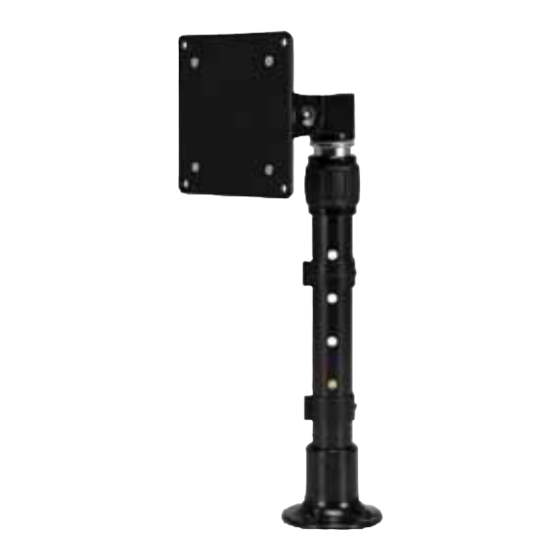
Description
A telescopic pedestal
B pivot head
C mounting base
D adapter plate
E M4 x 8mm countersink screw
F M4 x 10mm phillips screw
G wood screw #14 x 1
H hex bolt
I hex nut
J M4 x 0.7mm nut
K pressure plate
L nylon washer
M 4mm allen wrench
N 3mm allen wrench
NOTE: You may not use all hardware provided.
NOTE: Some parts may not appear exactly as illustrated.
A
LOCK BALL
C
2300 White Oak Circle • Aurora, Il 60502 • (800) 865-2112 • Fax: (800) 359-6500 • www.peerless-av.com
- Monitor Desktop Stand
LCH-100
Qty. Part #
1
091-1088
1
091-1090
1
091-1089
1
095-1100
4
520-1795
4
520-1796
4
510-9159
1
-
1
-
4
530-1082
1
-
1
540-1636
2
560-0072
1
560-0073
B
D
Models: LCH-100
MAX Load Capacity:
WARNING
SPRING LOADED PRODUCT
• Only release lock ball when screen is
installed. Do not place chin or object
above pole when releasing lock ball.
LCH-100
E
F
G
I
K
M
ISSUED: 09-30-02 SHEET #: 090-9085-6 07-23-13
25 lb (11.4KG)
H
J
L
N
Advertisement
Table of Contents

Related Manuals for peerless-AV LCH-100


Summary of Contents for peerless-AV LCH-100
- Page 1 NOTE: You may not use all hardware provided. NOTE: Some parts may not appear exactly as illustrated. LOCK BALL 2300 White Oak Circle • Aurora, Il 60502 • (800) 865-2112 • Fax: (800) 359-6500 • www.peerless-av.com ISSUED: 09-30-02 SHEET #: 090-9085-6 07-23-13...
- Page 2 CAUTION • Mount must be installed on wood and/or wood composition surfaces of at least 3/4" thick. However, the installer must ensure that the mounting surface will safely hold the combined weight of the mount and the screen. See other mounting requirements below.
- Page 3 To install to a VESA 75 mm standard LCD monitor, attach pivot head (B) to back of LCD monitor using four M4 x 10 mm phillips screws (F) as shown. Skip to step 6. To install to a VESA 100 mm standard LCD monitor, attach adapter plate (D) to pivot head (B) using four M4 x 8 mm phillips screws (E) and four M4 x 0.7mm nuts (J) as shown in detail 1.
- Page 4 Place nylon washer (L) and pivot head (B) on top pin of telescopic pedestal (A) as shown. To restrict rotation of LCD screen to 90°, lineup rear set screw with slot and tighten where shown in detail 3 using 3 mm allen wrench (N).
- Page 5 For tilt adjustment use one 4 mm allen wrench (M) to hold socket screw in place and the other 4 mm allen wrench (M) to turn the socket screw clockwise to tighten and counterclockwise to loosen as shown. SOCKET SCREW Turn screen clockwise by hand for landscape or portrait orientation.
Need help?
Do you have a question about the LCH-100 and is the answer not in the manual?
Questions and answers