Advertisement
Installation and Assembly - Vision•Point
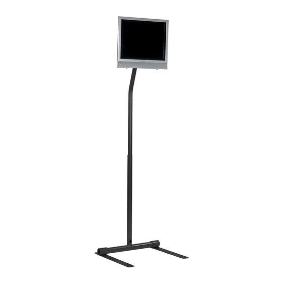
75/100 mm Adapter Plate
Read instruction sheet before you start installation and assembly.
Maximum Load Capacity:
25 lb (11.3 kg) - freestanding when feet are in outward
position
40 lb (18.1 kg) - bolted down to floor with screens over
25 lb or when feet are moved inwards
™
LCD Screen Pedestal Stand -
1 of 6
ISSUED:02-25-03 SHEET #: 095-9149-3 08-11-04
Model: LCFS 100,
LCFS 100S
Advertisement
Table of Contents

Related Manuals for peerless-AV LCFS 100


Summary of Contents for peerless-AV LCFS 100
- Page 1 ™ Installation and Assembly - Vision•Point LCD Screen Pedestal Stand - Model: LCFS 100, 75/100 mm Adapter Plate LCFS 100S Read instruction sheet before you start installation and assembly. Maximum Load Capacity: 25 lb (11.3 kg) - freestanding when feet are in outward position 40 lb (18.1 kg) - bolted down to floor with screens over...
- Page 2 Parts List Description Qty. LCFS 100 LCFS100S A base foot weldment 095-1152 095-4152 B main base weldment 095-1154 095-4154 C 75/100 mm LCD mount weldment 095-1156 095-4156 D main support tube 095-1157 095-4157 mating base tube 095-1134 095-4134 angled support tube...
- Page 3 WARNING • If base foot weldments (A) are positioned all the way outward, the Pedestal Stand can support up to a 25 lb (11.3 kg) LCD screen without being bolted down to the floor. If the base foot weldments (A) are positioned inward along the base and/or the screen weighs more than 25 lb, the Pedestal Stand MUST be bolted down to the floor.
- Page 4 Installation To Wood Floors Use a stud finder to find centers of floor joists. Use base foot weldments (A) as a template to mark holes. Drill four 3/16" (5 mm) dia. holes to a minimum depth of 1-1/4" (32 mm). Place four retaining spacers (M) over holes. Place base foot weldments (A) over retaining spacers (M) and secure with four #14 x 1-1/4"...
- Page 5 Insert angled support tube (F) into main support tube (D) in orientation shown. Adjust support tube (F) to the desired height. IMPORTANT: In the highest position, the support tube (F) must be inserted at least 3-1/2" in the support tube (D).
- Page 6 Run cords through cord management holes as shown. cord management hole cord management hole This product is designed to accommodate screens with VESA ® 75 or 100 compliant hole pattern. For safe mounting, please make sure that mounting screws turn at least three complete turns in the screen inserts.
Need help?
Do you have a question about the LCFS 100 and is the answer not in the manual?
Questions and answers