Table of Contents
Advertisement
Quick Links
Installation and Assembly:
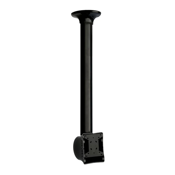
Ceiling mount for LCD screens up to 29"
Models: LCC18-C, LCC18-CS, LCC36-C, LCC36-CS
Features:
• Comes in two adjustable height ranges (in 1"
increments): 18"-30" and 36"-48"
• -5° to +20° adjustable tilt
• Screen can be mounted in standard position or
face-down
• Portrait or landscape orientation
• Ceiling plate included
• Hardware included for wood or concrete installa-
tions
•
Snap-together cover provides sleek aesthetics and
cord management
• Theft resistant security fasteners included
®
• VESA
75/100 mm compliant (Non-VESA adapter
offered separately)
• Comes in black and silver
• 360° swivel action
3215 W. North Ave. • Melrose Park, IL 60160 • (800) 729-0307 or (708) 865-8870 • Fax: (708) 865-2941 • www.peerless-av.com
Horizontal
Position
Max UL Load Capacity: 40 lb (18.1 kg)
ISSUED: 09-27-04 SHEET #: 100-9005-8 12-13-12
Vertical
Position
Advertisement
Table of Contents

Related Manuals for peerless-AV LCC 18-C


Summary of Contents for peerless-AV LCC 18-C
- Page 1 • Comes in black and silver • 360° swivel action Max UL Load Capacity: 40 lb (18.1 kg) 3215 W. North Ave. • Melrose Park, IL 60160 • (800) 729-0307 or (708) 865-8870 • Fax: (708) 865-2941 • www.peerless-av.com ISSUED: 09-27-04 SHEET #: 100-9005-8 12-13-12...
-
Page 2: Table Of Contents
Note: Read entire instruction sheet before you start installation and assembly. WARNING • Do not begin to install your Peerless product until you have read and understood the instructions and warnings contained in this Installation Sheet. If you have any questions regarding any of the instructions or warnings, please call Peerless customer care at 1-800-729-0307. -
Page 3: Parts List
Parts List LCC 18-C LCC 18-CS LCC 36-C LCC 36-CS Description Qty. Part # Part # Part # Part # tube assembly 055-1520 055-4520 055-1521 055-4521 ceiling plate 580-1042 580-4042 580-1042 580-4042 tilt bracket 055-1551 055-4551 055-1551 055-4551 reducer 580-1009... -
Page 4: Installation To Wood Joist Finished Ceilings, Exposed Wood Joists, Or Wood Beam Ceilings
Installation to Wood Joist Finished Ceilings, Exposed Wood Joists, or Wood Beam Ceilings WARNING • Installer must verify that the supporting surface will safely support the combined load of the equipment and all attached hardware and components. • Tighten wood screws so that wall plate is fi rmly attached, but do not overtighten. Overtightening can damage the screws, greatly reducing their holding power. -
Page 5: Installation To Concrete Ceilings
Installation to Concrete Ceilings WARNING • When installing Peerless wall mounts on cinder block, verify that you have a minimum of 1-3/8" (35 mm) of actual concrete thickness in the hole to be used for the concrete anchors. Do not drill into mortar joints! Be sure to mount in a solid part of the block, generally 1"... -
Page 6: Installing Reducer
Installing Reducer Thread reducer (D) onto tube assembly (A) until tight. Insert set screw (I) into reducer as shown in fi gure 2-1. Tighten screw using hex wrench (J). Note: Set screw (I) is used to jam against the threads of tube assembly to prevent any excess movement. -
Page 7: Flush Mount Installation
Flush Mount Installation Screw reducer (D) into ceiling plate (B) until notch in reducer is aligned with one of the four holes in ceiling plate and set screw (I) is at least partially covered by ceiling plate as shown in fi gure 3-1. Secure reducer with one M5 x 10 mm F-type socket pin screw (P) using security allen wrench (G) as shown in fi... -
Page 8: Installation To Extension Column
Installation to Extension Column Screw extension column (EXT or ADJ Series) to ceiling plate (B). Align the notch with one of the four holes in the ceiling plate and secure extension column with a M5 x 10 mm socket pin screw (P) using security allen wrench (G). -
Page 9: Installation To Lightweight Suspended Ceiling Plate
Installation to Lightweight Suspended Ceiling Plate Refer to instruction sheet for lightweight suspended ceiling plate (CMJ 455) for attachment of ceiling plate to ceiling. Screw extension column (EXT or ADJ Series) to retaining collar in ceiling tray. Align the notch with one of the four holes in retaining collar and secure extension column with one M5 x 10 mm socket pin screw (P) using security... -
Page 10: Attaching Tilt Bracket To Lcd Screen
Attaching Tilt Bracket to LCD Screen Note: This product is designed to accommodate screens with VESA ® compliant hole patterns. For safe mounting, please make sure that mounting screws turn at least three complete turns in the screen inserts. FOR VESA 75 MOUNTING PATTERN: 1) Choose hole pattern indicated below. -
Page 11: Installation Of Plasma In The Vertical Position
Installation of Screen in the Vertical Position Insert two M5 x 12 mm screws (F) into column bracket of tube assembly (A) (see fi gure 5-1). Leave approximately 3/16" of thread exposed (see fi gure 5.2). COLUMN 3/16" BRACKET EXPOSED THREAD fi... -
Page 12: Installation Of Plasma In The Horizontal Position
Installation of Screen in the Horizontal Position Insert two M5 x 12 mm screws (F) into column bracket of tube assembly (A) (see fi gure 5-1). Leave approximately 3/16" of thread exposed (see fi gure 5-2). 3/16" EXPOSED COLUMN THREAD BRACKET fi... -
Page 13: Installation Of Vertical Covers
Installation of Vertical Covers Route cords through side channels of one vertical cover (Q). Snap two vertical covers together on tube assembly (A) so that they are perpendicular to tilt bracket (C). If necessary, use a handsaw to cut vertical covers to match the length of tube assembly. -
Page 14: Installation Of Tilt Covers In The Vertical Position
Installation of Tilt Covers in the Vertical Position Using a carpenter's knife, cut out any sections of tilt covers (S) necessary to allow them to snap together over verti- cal covers (Q) as shown in fi gure 9-1. Note: Cut out sections of one tilt cover should mirror cut out sections of the other.
Need help?
Do you have a question about the LCC 18-C and is the answer not in the manual?
Questions and answers