Table of Contents
Advertisement
Quick Links
UM2756
User manual
SPC584BADPT176S Rev.A evaluation board
Introduction
The SPC584BADPT176S Rev.A evaluation board supports STMicroelectronics SPC584BxxE7, SPC584CxxE7 and
SPC58ECxxE7 microcontrollers in LQFP 176 package.
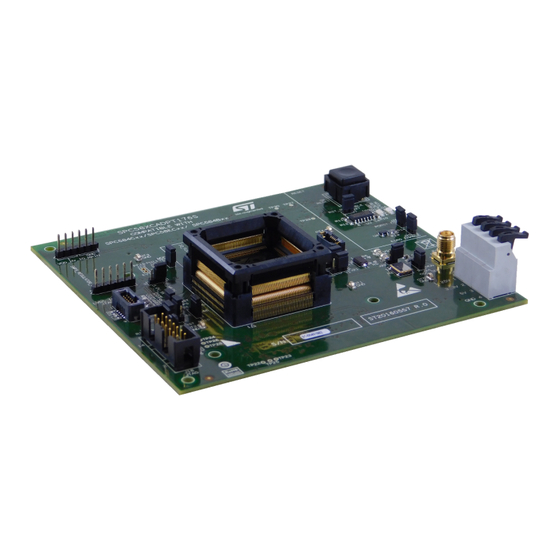
Figure 1.
SPC584BADPT176S Rev.A
Picture is not contractual
UM2756 - Rev 1 - August 2020
www.st.com
For further information contact your local STMicroelectronics sales office.
Advertisement
Table of Contents

Related Manuals for ST SPC584BADPT176S


Summary of Contents for ST SPC584BADPT176S
-
Page 1: Figure 1. Spc584Badpt176S Rev.a
UM2756 User manual SPC584BADPT176S Rev.A evaluation board Introduction The SPC584BADPT176S Rev.A evaluation board supports STMicroelectronics SPC584BxxE7, SPC584CxxE7 and SPC58ECxxE7 microcontrollers in LQFP 176 package. Figure 1. SPC584BADPT176S Rev.A Picture is not contractual UM2756 - Rev 1 - August 2020 www.st.com... -
Page 2: Overview
UM2756 Overview Overview The SPC584BADPT176S mini module is an evaluation board supporting STMicroelectronics SPC584BxxE7, SPC584CxxE7 and SPC58ECxxE7 microcontrollers in LQFP176 package. The mini module is designed to be connected onto the SPC58xxMB motherboard, offering a mechanism for easy customer evaluation of the supported devices, and to facilitate hardware and software development. -
Page 3: Package Contents
Overview of SPC584BADPT176S mini module - bottom Package contents An SPC584BADPT176S adapter package includes the following item: • SPC584BADPT176S mini module Supported devices The SPC584BADPT176S mini module supports the following STMicroelectronics family of microcontrollers in LQFP176 package: • SPC584BxxE7 • SPC584CxxE7 •... -
Page 4: License Agreement
Attention: This evaluation board only offers limited features for evaluating ST products. It has not been tested for use with other products and is not suitable for any safety or other commercial or consumer application. This evaluation board is otherwise provided “AS IS”... -
Page 5: Handling Precautions
UM2756 Handling precautions Handling precautions Please take care to handle the package contents in a manner such as to prevent electrostatic discharge. Before the EVB is used or power is applied, please fully read the following sections on how to correctly configure the board. -
Page 6: Features
UM2756 Hardware description Hardware description Hardware features The SPC584BADPT176S mini module board has the following features: • Connector for external power supplies input (5.0 V, 3.3 V, 1.25 V) used in stand-alone mode • Reset button with driver and led indicator •... -
Page 7: Power And System Configuration
When the mini module is plugged onto the motherboard, power is supplied directly by the motherboard. In this setup, the external power supply input available on the mini module should NOT be used. When the SPC584BADPT176S mini module is used as a stand-alone board, external power supplies must be used (5.0 V, 3.3 V, 1.25 V). -
Page 8: Port Configuration
The following jumper need to configure the ports: Table 2. Ports related jumpers Jumper Description Default Position Figure 4. SPC584BADPT176S top mini module view TESTMODE settings Close PH[12]/EVTI connection to QSH motherboard connectors Figure 4. SPC584BADPT176S top mini module view 1-2 (PH12) •... -
Page 9: Reset Circuit
Reset configuration jumpers Jumper Description Default Position Reset push button Open Figure 4. SPC584BADPT176S top mini module view - D1 Connect the external reset to the reset driver Close Figure 4. SPC584BADPT176S top mini module view - D1 ESR0 and PORST pins... -
Page 10: Connectors
Other connectors Connectors Description Position 12-pin header connector for SIPI interface Figure 4. SPC584BADPT176S top mini module view - C2 14-pin header connector for JTAG port Figure 4. SPC584BADPT176S top mini module view - A4 12-pin SAMTEC connector for JTAG/LFAST Figure 4. -
Page 11: Layout Overview
UM2756 Layout overview Layout overview Figure 4. SPC584BADPT176S top mini module view UM2756 - Rev 1 page 11/24... -
Page 12: Figure 5. Spc584Badpt176S Bottom Mini Module View
UM2756 Layout overview Figure 5. SPC584BADPT176S bottom mini module view UM2756 - Rev 1 page 12/24... -
Page 13: Bom
UM2756 Table 7. Item Qty Reference Manufacturer code Value Part description Samtec Samtec 5x2 TFM connector - 1.27 TFM-105-02-L-D-WT TFM-105-02-L-D- mm pitch - - with weld tabs C1, C3, C5, C7, C16, C18, C20, C22, C24, GCM188R71H104KA57D 100 nF Mult. cer. cap. 50V 0603 C58, C103 C2, C4, C6, C8, C17, C19, C21, C23, C25,... - Page 14 - SO14 74V1G08STR 74V1G08STR CMOS AND gate Quartz 40MHz NX5032GA XTAL NX5032GA 40 MHZ SPC584BADPT176S-CHORUS 2M CSSG20170421 R.0 MINIMODULE EQFP176 J1, J2 Bridge 2 pins female 2.54 mm pitch J3, J6, J7, J13, J21, J23, J24, J31, J41, J42,...
-
Page 15: Schematics
47nF 10nF 2.2uF 47nF 10nF 2.2uF 47nF 10nF 2.2uF 47nF 10nF 2.2uF SPC58NE84_176ELQ FP BCTRL / PM[15] SPC584BADPT176S eQFP176 POWER PINS STR IP 2mm VDD_HV_IO_MAIN 5.0V_SR C123 C124 AGND VSS_OSC NJD2873 D-PAK SMPS_REGULA TOR_OUT C125 the rm al plane ,... -
Page 16: Figure 7. Microcontroller I/O
PD[13] PC14 PD14 PC [14] PD[14] PC15 PD15 PC [15] PD[15] PA_9 (pg6) PE [0..15] PF[0..15] (pg5,6) SPC584BADPT176S eQFP176 (pg4) TDO_RxD ATA_P PE [0] PF[0] SIGNALS PE [1] PF[1] STRI P 2mm PE [2] PF[2] PE [3] PF[3] PE [4]... -
Page 17: Figure 8. Jtag, Jtag Lfast And Nexus
Figure 8. JTAG, JTAG LFAST and Nexus JTAG interface JTAG/LFAST LVDS INTERFACE 10 Pin Versio n 47nF Place CAPS as close to VDD_HV_IO_JTAG VDD_HV_IO_JTAG VDD_HV_IO_JTAG connector pins as possible but do NOT fit 47nF caps at board assembly. VDD_HV_IO_JTAG JCOMP C132 0603 JTAG Connector... -
Page 18: Figure 9. Clock And Reset Circuit
Figure 9. Clock and reset circuit External oscillato r External clock inpu t EVB-EXTAL EVB-EXTAL 3.3V_SR EXTAL 100nF EXTAL (pg3) (MCU Crystal Input) STRIP 2mm STRIP 2mm Note - External 3.3V regulator MUST be 40MHZ enabled when using Note - Internal oscillator module Pull-Up on Pin 1 XTAL... -
Page 19: Figure 10. Board Connector
Figure 10. Board connector PortA PortB PortC PortD PortE PortF PortG PortH PortI PortJ PA[0..15] PB [0..15] PC[0..15] PD[0..15] PE [0..15] PF[0..15] PG [0..15] PH[0..15] PI[0..15] PJ[0..4] (pg4) PA[0..15] (pg4) PB [0..15] (pg4) PC[0..15] (pg4) PD[0..15 ] (pg4) PE [0..15] (pg4,6) PF[0..15] (pg4) -
Page 20: Revision History
UM2756 Revision history Table 8. Document revision history Date Version Changes 05-Aug-2020 Initial release. UM2756 - Rev 1 page 20/24... -
Page 21: Table Of Contents
UM2756 Contents Contents Overview ................2 Package Contents. - Page 22 UM2756 List of tables List of tables Table 1. Power configuration jumpers ............7 Table 2.
- Page 23 Overview of SPC584BADPT176S mini module - bottom........
- Page 24 ST’s terms and conditions of sale in place at the time of order acknowledgement. Purchasers are solely responsible for the choice, selection, and use of ST products and ST assumes no liability for application assistance or the design of Purchasers’...
Need help?
Do you have a question about the SPC584BADPT176S and is the answer not in the manual?
Questions and answers