Table of Contents
Advertisement
Quick Links
UM2869
User manual
SPC572LADPT80S evaluation board
Introduction
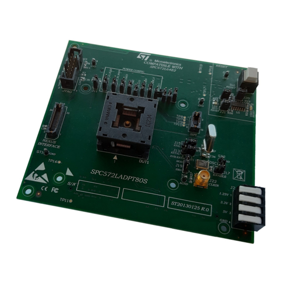
The SPC572LADPT80S evaluation board supports STMicroelectronics SPC572L64E2 microcontroller in TQFP80-EP package.
Figure 1.
SPC572LADPT80S
Note: picture not contractual.
UM2869 - Rev 1 - June 2021
www.st.com
For further information contact your local STMicroelectronics sales office.
Advertisement
Table of Contents

Related Manuals for ST SPC572LADPT80S


Summary of Contents for ST SPC572LADPT80S
- Page 1 UM2869 User manual SPC572LADPT80S evaluation board Introduction The SPC572LADPT80S evaluation board supports STMicroelectronics SPC572L64E2 microcontroller in TQFP80-EP package. Figure 1. SPC572LADPT80S Note: picture not contractual. UM2869 - Rev 1 - June 2021 www.st.com For further information contact your local STMicroelectronics sales office.
-
Page 2: Overview
High density connectors provide the interface between the EVB and MCU daughter cards and help the developers evaluate all device peripherals. This user manual provides information on how to use the SPC572LADPT80S "mini module" board and its hardware features. -
Page 3: Supported Devices
UM2869 Supported devices Figure 3. Overview of SPC572LADPT80S "mini module" - bottom Supported devices The SPC572LADPT80S evaluation board supports the following STMicroelectronics family of microcontrollers in TQFP80-EP package: • SPC572L64E2 UM2869 - Rev 1 page 3/29... -
Page 4: License Agreement
Attention: This evaluation board only offers limited features for evaluating ST products. It has not been tested for use with other products and is not suitable for any safety or other commercial or consumer application. This evaluation board is otherwise provided “AS IS”... -
Page 5: Handling Precautions
UM2869 Handling precautions Handling precautions Please take care to handle the package content in order to prevent electrostatic discharge. Before the EVB is used or power is applied, please fully read the following sections on how to correctly configure the board. Failure to correctly configure the board may cause irreparable component, MCU or EVB damage. UM2869 - Rev 1 page 5/29... -
Page 6: Features
UM2869 Hardware description Hardware description Hardware features The SPC572LADPT80S "mini module" board has the following features: • Can be used as a stand-alone board by providing external power supplies input (5 V, 3.3 V, 1.25 V) • Reset button with driver and led indicator •... -
Page 7: Figure 5. Overview Of 6-Pin Jumpers Numbering Convention
UM2869 Pins numbering for jumpers 6-pin jumpers for the “mini module” have the PCB serigraphy with the numbers of all pins. See the example below for the numbering convention used in this manual for jumpers settings: Figure 5. Overview of 6-pin jumpers numbering convention UM2869 - Rev 1 page 7/29... -
Page 8: Power And System Configuration
When the "mini module" is plugged onto the motherboard, power is supplied directly by the motherboard. In this setup, the external power supply input available on the "mini module" should NOT be used. When the SPC572LADPT80S "mini module" is used as a stand-alone board, external power supplies must be used (5 V, 3.3 V, 1.25 V). -
Page 9: Port Configuration
Ports related jumpers Jumper Description Default Position PD[6] connection to QSH connectors configuration: • Open: PD[6] not connected to QSH connectors Figure 10. SPC572LADPT80S "mini module" (motherboard) Closed - top - C2 • Closed: PD[6] connected to QSH connectors (motherboard) PD[6] connection to EVTI configuration: Figure 10. -
Page 10: System Clock Configuration
Jumper Description Default Position • EXTAL connection configuration: – 1-2: EXTAL connected to 40 MHz crystal Figure 10. SPC572LADPT80S "mini module" - clock source - C3 (XT1 pin2) – 2-3: EXTAL connected to EXTAL EVB clock source • XTAL connection configuration: –... -
Page 11: Reset Circuit
Table 5. Connectors Connectors Description Position Figure 10. SPC572LADPT80S "mini module" - top 14-pin header connector for JTAG port Figure 10. SPC572LADPT80S "mini module" - top 34-pin SAMTEC connector for Nexus 2 Figure 10. SPC572LADPT80S "mini module" - top 10-pin SIPI interface connector Figure 10. -
Page 12: Table 6. Jtag Header 2X7 Pins Connector Pinout
UM2869 Connectors The following figure shows the JTAG connector scheme: Figure 6. JTAG connector scheme The following table shows the JTAG connector pinout: Table 6. JTAG Header 2x7 pins connector pinout Pin number Signal EVTI PORST ESR0 VDD_HV_IO_MAIN EVTO N.C. UM2869 - Rev 1 page 12/29... -
Page 13: Table 7. Nexus Samtec Asp-137973-01 Connector Pinout
UM2869 Connectors Figure 7. NEXUS SAMTEC ASP-137973-01 Table 7. NEXUS SAMTEC ASP-137973-01 connector pinout Pin number Signal N.C. 3.3 V N.C. TX1P TX1N JCOMP N.C. N.C. N.C. EVTI UM2869 - Rev 1 page 13/29... -
Page 14: Figure 8. Sipi Interface Scheme
UM2869 Connectors Pin number Signal EVTO N.C. PORST N.C. ESR0 N.C. N.C. N.C. N.C. N.C. N.C. N.C. N.C. The following figure shows the SIPI interface scheme: Figure 8. SIPI interface scheme UM2869 - Rev 1 page 14/29... -
Page 15: Table 8. Sipi Interface Connector Pinout
UM2869 Connectors The following picture shows the SIPI interface connector pinout: Table 8. SIPI interface connector pinout Pin number Signal SIPI_TXP SIPI_TXN DRCLK SIPI_RXN SIPI_RXP The following figure shows the external power supply connector scheme: Figure 9. External power supply connector scheme Table 9. -
Page 16: Configuration For Pin Shared
Test points Test points Several test points of different shape and functionality are scattered around the SPC572LADPT80S evaluation board to allow easy access to MCU and reference signals. This chapter summarizes and describes the available test points. Test points are listed and detailed in the following table. -
Page 17: Layout Overview
UM2869 Layout overview Layout overview Figure 10. SPC572LADPT80S "mini module" - top UM2869 - Rev 1 page 17/29... -
Page 18: Figure 11. Spc572Ladpt80S "Mini Module" - Bottom
UM2869 Layout overview Figure 11. SPC572LADPT80S "mini module" - bottom UM2869 - Rev 1 page 18/29... -
Page 19: Bom
UM2869 Table 11. Item Reference Value Option Description Mult. cer. cap. CCERSMD225-0805M 2.2 uF 16V SMD 0805 - automotive series C2, C5, C8, C10, Mult. cer. cap. 50V C13, C16, C19, C22, CCERSMD104-0603M 100 nF SMD 0603 C29, C32, C39 C3, C6, C9, C11, Mult. -
Page 20: Table 11. Bom
UM2869 Item Reference Value Option Description SAMTEC 0.5 mm SAMTEC J23, J24 SAM-QSH12001LDA pitch high speed SMD QSH-120-01-L-D-A socket Close JP2, JP5 Jumper SMD JP3, JP8, JP10, Jumper SMD JP11, JP12 JP7, JP9 Closed Jumper SMD Led diode yellow LEDSMDGIAL-0805 Yellow SMD 0805 Led diode red SMD... -
Page 21: Schematics
CLOSED I / O ( 3. 3v - 5V) VDD_HV_IO_MAIN3 VDD_HV_IO_MAIN VDD_HV_IO_MAIN2 VDD_HV_IO_MAIN VDD_HV_IO_MAIN1 STRIP3PM 100nF 4.7uF 100nF 4.7uF 100nF 4.7uF DEFAULT SPC572LADPT80S Power Pi ns 100V 100V 100V 1-2 CLOSED 0603 0603 0805 0603 0603 0805 0603 0603 0805... -
Page 22: Figure 13. Signals
Figure 13. Signals TP2 TP3 TP4 TP5 TP6 DEFAULT 1-2 CLOSED TRST TRST SOLDER JUMER DRCLK DEFAULT 1-2 CLOSED SIPI_TXP SOLDER JUMER PA[0..15] PE[0..15] DUT1B PE[0] PA[1] PE[1] PA[2] PA[3] PA[5] JP10 PA[6] JP11 THESE JUMPERS PA[7] JP12 PA[8] ARE NORMALLY OPEN PA[9] PE[9] PA10... -
Page 23: Figure 14. Reset Jtag, Sipi, Nexus Interface And Crystal Oscillator
Figure 14. Reset JTAG, SIPI, Nexus interface and crystal oscillator VDD_HV_OSC0 Jtag interface VDD_HV_OSC0 0R DNP JTAG Connector NOT MOUNTED 1/10W 0603 10K DNP NOT MOUNTED 1/10W 0603 EVTI PORST EVTI PORST ESR0 ESR0 EVTO EVTO TRST N2514-6002RB NOT MOUNTED 47pF DNP 27pF EVB-EXTAL... -
Page 24: Figure 15. Daughter Card And Motherboard Connectors
Figure 15. Daughter card and motherboard connectors PortA PortB PortC PortD PortF PortG PortE PA[0..15 ] PB[0..15] PC[0..15] PD[0..15] PE[0..15] PF[0..15] PG[1..15] PA[0..15 ] PB[0..15] PC[0..15] PD[0..15] PE[0..15] PF[0..15] PG[1..15] PA10 PB10 PC10 PA11 PB11 PC11 PD11 PA12 PB12 PC12 PE12 PA13 PB13... -
Page 25: Revision History
UM2869 Revision history Table 12. Document revision history Date Version Changes 03-Jun-2021 Initial release. UM2869 - Rev 1 page 25/29... -
Page 26: Table Of Contents
UM2869 Contents Contents Overview ................2 Supported Devices . - Page 27 UM2869 List of tables List of tables Table 1. Power supplies configuration jumpers............8 Table 2.
- Page 28 Overview of SPC572LADPT80S "mini module" - bottom ........
- Page 29 ST’s terms and conditions of sale in place at the time of order acknowledgement. Purchasers are solely responsible for the choice, selection, and use of ST products and ST assumes no liability for application assistance or the design of Purchasers’...
Need help?
Do you have a question about the SPC572LADPT80S and is the answer not in the manual?
Questions and answers