Table of Contents
Advertisement
Quick Links
Advertisement
Table of Contents

Subscribe to Our Youtube Channel
Related Manuals for ST SPC58XXMB


Summary of Contents for ST SPC58XXMB
-
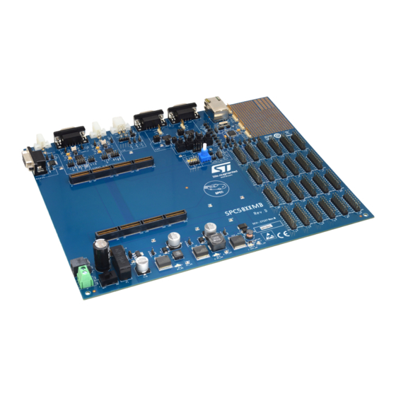
Page 1: Figure 1. Spc58Xxmb
UM2740 User manual SPC58XXMB evaluation board Introduction This document describes the STMicroelectronics SPC58XXMB evaluation board. Figure 1. SPC58XXMB UM2740 - Rev 1 - January 2021 www.st.com For further information contact your local STMicroelectronics sales office. -
Page 2: Overview
Overview Overview This user’s manual details the setup and configuration of the STMicroelectronics SPC58XXMB evaluation board (hereafter referred to as the EVB). The EVB is intended to provide a mechanism for easy customer evaluation of the SPC58xx family and SPC57xx family of microcontrollers, and to facilitate hardware and software development. -
Page 3: License Agreement
Attention: This evaluation board only offers limited features for evaluating ST products. It has not been tested for use with other products and is not suitable for any safety or other commercial or consumer application. This evaluation board is otherwise provided “AS IS”... -
Page 4: Handling Precautions
UM2740 Handling precautions Handling precautions Please take care to handle the package contents in a manner such as to prevent electrostatic discharge. Before the EVB is used or power is applied, please fully read the following sections on how to correctly configure the board. -
Page 5: Hardware Description
UM2740 Hardware description Hardware description List of acronyms The table below provides a list and description of acronyms used throughout this document. Table 1. List of acronyms Acronym Description 1.25V_SR Supply voltage from the 1.25 V switching regulator 3.3V_SR Supply voltage from the 3.3 V switching regulator 5V_LR Supply voltage from the 5.0 V linear regulator 5V_SR... -
Page 6: Modular Concept
UM2740 Modular concept Modular concept For maximum flexibility and simplicity, the EVB has been designed as a modular development platform. The EVB main board does not contain an MCU. Instead, the MCU is fitted to an MCU daughter card (occasionally referred to as an adapter board). -
Page 7: Daughter Card Availability
UM2740 Daughter card availability Daughter card availability Table 2. Daughter card Daughter card number Device SPC58NHADPT176S SPC58NHxxE7 SPC58NHADPT302S SPC58NHxxC3 SPC58NHADPT386S SPC58NHxxC5 SPC584BxxE7 SPC58XCADPT176S SPC58xCxxE7 SPC58XCADPT292S SPC584CxxC5 SPC582BxxE1 SPC58XXADPT64S SPC584BxxE1 SPC58xCxxE1 SPC582BxxE3 SPC584BxxE3 SPC58XXADPT100S SPC58xCxxE3 SPC58xGxxE3 SPC582BxxE5 SPC584BxxE5 SPC58XXADPT144S SPC58xCxxE5 SPC58xGxxE5 SPC58xGxxE3 SPC58XXADPT176S SPC58xExxE3... -
Page 8: Evb Features
UM2740 EVB features EVB features The EVB system consists of a motherboard and a daughter card, both with distinct features. The mother board provides the following key features: • Support provided for different SPC58xx MCUs and SPC57xx MCUs by utilizing MCU daughter cards •... -
Page 9: Configuration
UM2740 Configuration Configuration This section details the configuration of each of the EVB functional blocks. The EVB has been designed keeping in mind the ease of use, and has been segmented into functional blocks as shown in the figure below. A detailed silkscreen legend has been used throughout the board to identify all switches, jumpers and user connectors. -
Page 10: Power Supply Configuration
UM2740 Power supply configuration Power supply configuration The EVB requires an external power supply voltage of 12 V DC, minimum 1 A. This allows the EVB to be easily used in a vehicle if required. The single input voltage is regulated on-board using three switching regulators to provide the necessary EVB and MCU operating voltages of 5.0 V, 3.3 V and 1.25 V, and one 5 V linear regulator for the ADC supplies and references. -
Page 11: Regulator Power Jumpers
UM2740 Regulator power jumpers Regulator power jumpers There are four power regulator circuits on the SPC58xx motherboard that supply the required voltages to operate the MCUs: • 1.25V_SR: 1.25 V switching regulator to supply the core voltage • 5V_SR: 5 V switching regulator to supply the power management controller, I/O and peripherals •... -
Page 12: Can Configuration
UM2740 CAN configuration 4.11 CAN configuration The EVB has two high speed CAN FD transceivers and two female standard DB9 connectors to provide physical CAN FD interfaces for the MCU. The pinout of the DB9 female connector (J5) is shown in the below figure. Figure 6. -
Page 13: Rs232 Configuration
UM2740 RS232 configuration Table 3. CAN control jumpers Jumper Label Description PHY U2 configuration 1-2: WAKE to GND CAN2_EN 3-4: STB to 5 V 5-6: EN to 5 V 1-2: PHY TX to MCU CAN2 3-4: PHY RX to MCU 1-2: 5.0V_SR to PHY U2 VCC CAN-PWR 3-4: 12 V to PHY U2 VBAT... -
Page 14: Lin Configuration
UM2740 LIN configuration By default the RS232 interface is not enabled. The user needs to place the jumpers detailed in Table 4. RS232 control jumpers to enable the RS232 interface. Table 4. RS232 control jumpers Jumper Label Description SCI TX TX enable SCI RX RX enable... -
Page 15: Flexray Configuration
UM2740 FlexRAY configuration Table 5. LIN control jumpers Jumper Label Description LIN_EN LIN PHY (U50) enable LIN_RX LIN RX enable LIN_TX LIN TX enable 4.14 FlexRAY configuration The EVB is fitted with two FlexRAY transceivers, a female DB9 connector (for both transceivers) and two alternative connectors. -
Page 16: Table 6. Flexray Control Jumpers
UM2740 FlexRAY configuration Table 6. FlexRAY control jumpers Jumper Label Description FlexRay transceiver VIO selection 1-2: 12 V to VBAT FR_PWR 3-4: 5V_SR to VCC and VBUF 5-6: 3.3V_SR to VIO 1-2: PHY U4 TX to MCU FR_A 3-4: PHY U4 TXEN to MCU 5-6: PHY U4 RX to MCU PHY U4 configuration: 1-2: 3.3 V (VIO) to BGE... -
Page 17: Ethernet Configuration
UM2740 Ethernet configuration 4.15 Ethernet configuration The EVB is fitted with a standard RJ45 Ethernet connector (J7) and an Ethernet transceiver (U6). By default, the Ethernet interface is not enabled. To enable the Ethernet interface the jumpers detailed in Table 5. LIN control jumpers need to be placed. -
Page 18: Motherboard Test Points
UM2740 Motherboard test points 4.16 Motherboard test points Several test points of different shapes and functionalities are scattered around the EVB to allow an easy access to MCU and reference signals. This chapter summarizes and describes the available test points. Motherboard test points are listed and detailed in the below table. - Page 19 UM2740 Motherboard test points Signal TP name Shape Description FRB-INH2 FlexRAY FRB-INH1 FlexRAY FRB-ERRN FlexRAY FRB-RXEN FlexRAY FR_DBG0 TP10 FlexRAY debug0 FR_DBG1 TP11 FlexRAY debug1 FR_DBG2 TP12 FlexRAY debug2 FR_DBG3 TP13 FlexRAY debug3 FEC 25MHz Ethernet clock UM2740 - Rev 1 page 19/45...
-
Page 20: Board Interface Connectors
UM2740 Board interface connectors 4.17 Board interface connectors This chapter provides a useful cross reference to see the connection from the motherboard to the board interface connector, and what MCU pins are connected to the interface connector on the daughter cards. Table 7. - Page 21 UM2740 Board interface connectors Connector Motherboard Connector Motherboard A-32 B-209 A-33 B-208 A-34 B-207 A-35 PC10 B-206 PD10 A-36 PC11 B-205 PD11 A-37 PC12 B-204 PD12 A-38 PC13 B-203 PD13 A-39 PC14 B-202 PD14 A-40 PC15 B-201 PD15 A-41 3.3V_SR B-200 3.3V_SR A-42...
- Page 22 UM2740 Board interface connectors Connector Motherboard Connector Motherboard A-73 B-168 A-74 B-167 A-75 PG10 B-166 PH10 A-76 PG11 B-165 PH11 A-77 PG12 B-164 PH12 A-78 PG13 B-163 PH13 A-79 PG14 B-162 PH14 A-80 PG15 B-161 PH15 A-81 5.0V_SR B-160 3.3V_SR A-82 5.0V_SR B-159...
- Page 23 UM2740 Board interface connectors Connector Motherboard Connector Motherboard A-114 B-127 A-115 PK10 B-126 PL10 A-116 PK11 B-125 PL11 A-117 PK12 B-124 PL12 A-118 PK13 B-123 PL13 A-119 PK14 B-122 PL14 A-120 PK15 B-121 PL15 A-121 5.0V_LR B-120 5.0V_LR A-122 5.0V_LR B-119 5.0V_LR A-123...
- Page 24 UM2740 Board interface connectors Connector Motherboard Connector Motherboard A-155 PO10 B-86 PP10 A-156 PO11 B-85 PP11 A-157 PO12 B-84 PP12 A-158 PO13 B-83 PP13 A-159 PO14 B-82 PP14 A-160 PO15 B-81 PP15 A-161 1.25V_SR B-80 1.25V_SR A-162 1.25V_SR B-79 1.25V_SR A-163 1.25V_SR B-78...
- Page 25 UM2740 Board interface connectors Connector Motherboard Connector Motherboard A-196 PS11 B-45 PT11 A-197 PS12 B-44 PT12 A-198 PS13 B-43 PT13 A-199 PS14 B-42 PT14 A-200 PS15 B-41 PT15 A-201 3.3V_SR B-40 3.3V_SR A-202 3.3V_SR B-39 3.3V_SR A-203 3.3V_SR B-38 3.3V_SR A-204 3.3V_SR B-37...
- Page 26 UM2740 Board interface connectors Connector Motherboard Connector Motherboard A-237 PW12 PX12 A-238 PW13 PX13 A-239 PW14 PX14 A-240 PW15 PX15 UM2740 - Rev 1 page 26/45...
-
Page 27: Default Jumper Summary Table
UM2740 Default jumper summary table Default jumper summary table The following table details the DEFAULT jumper configuration of the EVB as set up on delivery. Default jumper table - motherboard On delivery the motherboard comes with a default jumper configuration. The table below lists and describes briefly the jumpers on the MPC58xx motherboard and indicates which jumpers are on/off on delivery of the board. - Page 28 UM2740 Default jumper table - motherboard Jumper Default Pos PCB Legend Description FlexRAY transceiver VIO selection FR_PWR 1-2: 12 V to VBAT 3-4: 5V_SR to VCC and VBUF 1-2: PHY U5 TX to MCU FR_B 3-4: PHY U5 TXEN to MCU 5-6: PHY U5 RX to MCU PHY U5 configuration: 1-2: 3.3 V (VIO) to BGE...
-
Page 29: User Area
UM2740 User area Jumper Default Pos PCB Legend Description DISABLE Disable 5.0 V switching regulator User area There is a rectangular prototype area on the EVB’s top right corner, consisting of a 0.1-inch pitch array of through-hole plated pads. Power from all the three switching regulators is readily accessible along with GND through JP1 –... -
Page 30: Bom
UM2740 Table 11. Itm Qty Reference Part number Part name Part description C1, C2, C7, C8, C11, Tantalum Cap SMD - 10µF 10V - case A CTAN SMD 106-A-10 10µF - AVX C3, C4, C5, C6, C51, C52, C58, C65, C66, C70, C73, C74, C75, Ceramic Cap. - Page 31 UM2740 Itm Qty Reference Part number Part name Part description JP1, JP2, JP3, JP4, JP5, JP6, JP7, JP8, JP9, JP10, JP11, SAM- HTSW10107SMS HDR 1X1 HDR 1X1 TH -- 330H AU 100L JP12, JP13, JP14, JP15, JP16 J1, J3 MOLEX2P-39291028 Cap.
-
Page 32: Table 11. Bom
UM2740 Itm Qty Reference Part number Part name Part description Resistor array 10K SMD CASE 1206 RN2, RN50, RN51 RRSMD-103-1206 10 K SERIE CAY 16 Resistor array 470R SMD CASE 1206 RN55 RRSMD-471-1206 470R SERIE CAY 16 Resistor array 22R SMD CASES 0804 RN52, RN53, RN54 RRSMD-220-0804 SERIES CAY 10... -
Page 33: Schematic
Schematic Figure 13. Power Input, Linear and Switchers S witc hing Re g ulato rs Po we r s upply input and filte r S W5 G-107-0513 2.1mm Barrel P12V Connector P12V L3 47UH 0.1UF INPUT C_BOOST 12V-IN VSwitche d VFus e d 47UH 5.0V_SR... -
Page 34: Figure 14. Mother Board Connector
Figure 14. Mother board connector PortA PortB PortC PortD PortE PortF PortG PortH PortI PortJ PortK PortL PA[0..15] PB[0..15] P C[0..15] PD[0..15] P E[0..15] PF[0..15] PG[0..15] P H[0..15] PI[0..15] PJ [0..15] PK[0..15] PL[0..15] (pg5,9) PA[0..15] (pg9,10) PB[0..15] (pg5,8,9) PC[0..15] (pg6,9) PD[0..15] (pg5..9) PE[0..15]... -
Page 35: Figure 15. Can Interface
Figure 15. CAN interface P12V 5.0V_SR CAN-5V MCAN2 J 33 0.1UF 1000PF CAN-12V 0.1UF 1000PF VDD_HV_IO_MAIN 0.1UF 1000PF J 34 MCAN1-CANH CANH MCAN1-CANL HDR 1X2 WAKE P C9 (CNA-TX) J 32 (pg4,9) CANL MCAN1-TX MCAN1-RX P C8 (CNA-RX) (pg4,9) SPLIT 60.4 60.4 J 23... -
Page 36: Figure 16. Spi/Rs232 And Lin Interface
Figure 16. SPI/RS232 and LIN interface e S C I / R S 2 3 2 a n d L I N P H Y S I C A L I N T E R F A C E S e S CI / RS 232 VDD_HV_IO_MAIN VDD_HV_IO_MAIN... -
Page 37: Figure 17. Flexray
Figure 17. FlexRay Fle xRay_A VDD_HV_IO_FLEX 5.0V_SR P 12V J 29 HDR 2X3 FR-12V FR-5V J29 Default: FR-VIO Across pin1 & pin2 VIO Selection Jumper Across pin3 & pin4 HDR 1X2 FR-VIO Across pin5 & pin6 FR-5V (pg4,9) PH[0..15] FR-12V 0.1UF 0.1UF 10UF... -
Page 38: Figure 18. Fast Ethernet Controller
Figure 18. Fast Ethernet controller ETHERNET PHYSICAL INTERFACE AND RJ45 TX Resistors: Place Close to PI PA15 (pg4,9) PA15 RX Resistors: Place Close to MCU 3.3V_SR PE12 (pg4,7,9) PE12 J 22 These lines need to be matched! HDR 1X2 PC15 0.1UF 10UF 0.1UF... -
Page 39: Figure 19. User I/O
Figure 19. User I/O PA[0..15] PI[0..15] PQ[0..15] PQ[0..15] (pg4,5) PA[0..15] (pg4) PI[0..15] PQ[0..15] (pg4) PortA PortI PortQ PA10 PA11 PI10 PI11 PQ10 PQ11 PA12 PA13 PI12 PI13 PQ12 PQ13 PA14 PA15 PI14 PI15 PQ14 PQ15 HDR 2X9 HDR 2X9 HDR 2X9 PB[0..15] PJ [0..15] PR[0..15]... -
Page 40: Figure 20. User Peripherals Inc. Prototyping
Figure 20. User peripherals inc. prototyping AN0 Po te ntio me te r/Filte rs /Vo ltag e Mo nito rs Us e r LED's Us e r S witc he s VDD_HV_IO_MAIN (Note - This is run from linear 5.0v regulator to provide a stable input voltage) US R-SW1 5.0V_LR YELLOW LED... -
Page 41: Revision History
UM2740 Revision history Table 12. Document revision history Date Version Changes 25-Jan-2021 Initial release. UM2740 - Rev 1 page 41/45... -
Page 42: Table Of Contents
UM2740 Contents Contents Overview ................2 Package contents . - Page 43 UM2740 List of tables List of tables Table 1. List of acronyms ..............5 Table 2.
- Page 44 SPC58XXMB ........
- Page 45 ST’s terms and conditions of sale in place at the time of order acknowledgement. Purchasers are solely responsible for the choice, selection, and use of ST products and ST assumes no liability for application assistance or the design of Purchasers’...
Need help?
Do you have a question about the SPC58XXMB and is the answer not in the manual?
Questions and answers