Table of Contents
Advertisement
Quick Links
UM2790
User manual
SPC58XXADPT64S rev. B evaluation board
Introduction
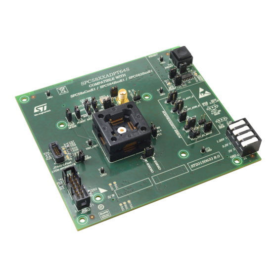
The SPC58XXADPT64S rev. B evaluation board supports STMicroelectronics SPC582BxxE1, SPC584BxxE1 and
SPC58xCxxE1 microcontrollers in eTQFP64 package.
Figure 1.
SPC58XXADPT64S rev. B
UM2790 - Rev 1 - February 2021
www.st.com
For further information contact your local STMicroelectronics sales office.
Advertisement
Table of Contents

Subscribe to Our Youtube Channel
Related Manuals for ST SPC58XXADPT64S


Summary of Contents for ST SPC58XXADPT64S
- Page 1 UM2790 User manual SPC58XXADPT64S rev. B evaluation board Introduction The SPC58XXADPT64S rev. B evaluation board supports STMicroelectronics SPC582BxxE1, SPC584BxxE1 and SPC58xCxxE1 microcontrollers in eTQFP64 package. Figure 1. SPC58XXADPT64S rev. B UM2790 - Rev 1 - February 2021 www.st.com For further information contact your local STMicroelectronics sales office.
-
Page 2: Overview
The "mini module" may be used as a stand-alone unit granting access to the CPU, but no access to the I/O pins as any motherboard peripherals. The SPC58XXADPT64S rev. B "mini module" is designed to be easily configurable and to be used for SPC582BxxE1, SPC584BxxE1 and SPC58xCxxE1. -
Page 3: Package Contents
Package contents An SPC58XXADPT64S rev. B adapter package includes the following item: • SPC58XXADPT64S rev. B "mini module" Supported devices The SPC58XXADPT64S rev. B "mini module" supports the following STMicroelectronics family of microcontrollers in eTQFP64 package: • SPC582BxxE1 • SPC584BxxE1 •... -
Page 4: License Agreement
Attention: This evaluation board only offers limited features for evaluating ST products. It has not been tested for use with other products and is not suitable for any safety or other commercial or consumer application. This evaluation board is otherwise provided “AS IS”... -
Page 5: Handling Precautions
UM2790 Handling precautions Handling precautions Please take care to handle the package contents in a manner such as to prevent electrostatic discharge. Before the EVB is used or power is applied, please fully read the following sections on how to correctly configure the board. -
Page 6: Hardware Description
UM2790 Hardware description Hardware description Hardware features The SPC58XXADPT64S rev. B "mini module" board has the following features: • Connector for external power supplies input (5.0 V, 3.3 V, 1.25 V) used in stand-alone mode • Reset button with driver and led indicator •... -
Page 7: Power And System Configuration
When the "mini module" is plugged onto the motherboard, power is supplied directly by the motherboard. In this setup, the external power supply input available on the "mini module" should NOT be used. When the SPC58XXADPT64S rev.B "mini module" is used as a stand-alone board, external power supplies must be used (5.0 V, 3.3 V, 1.25 V). -
Page 8: Microcontrollers Configuration
UM2790 Microcontrollers configuration Microcontrollers configuration The SPC58XXADPT64S rev. B "mini module" is designed to be easily configurable and be used for SPC582BxxE1, SPC584BxxE1 and SPC58xCxxE1. The "mini module" is configured by default for SPC582BxxE1 and easily supports SPC584BxxE1 and SPC58xCxxE1 by simply changing the following through-hole jumper JR19. -
Page 9: System Clock Configuration
Jumper Description Default Position 40 MHz crystal clock source enable Figure 4. SPC58XXADPT64S rev. B "mini module" - top 1-2 (XT1 pin2) for pin EXTAL 40 MHz crystal clock source enable Figure 4. SPC58XXADPT64S rev. B "mini module" - top... -
Page 10: Reset Circuit
Jumper Description Default Position Reset push button Open Figure 4. SPC58XXADPT64S rev. B "mini module" - top - D1 Connect the external reset to the reset driver for Close Figure 4. SPC58XXADPT64S rev. B "mini module" - top - D1... - Page 11 Connectors Connectors Description Position 10-pin header connector for JTAG/LFAST Figure 4. SPC58XXADPT64S rev. B "mini module" - top - A2 LVDS interface Fault collection and control unit (FCCU) pin, Figure 4. SPC58XXADPT64S rev. B "mini module" - top - C2...
-
Page 12: Layout Overview
UM2790 Layout overview Layout overview Figure 4. SPC58XXADPT64S rev. B "mini module" - top UM2790 - Rev 1 page 12/24... -
Page 13: Figure 5. Spc58Xxadpt64S Rev. B "Mini Module" - Bottom
UM2790 Layout overview Figure 5. SPC58XXADPT64S rev. B "mini module" - bottom UM2790 - Rev 1 page 13/24... -
Page 14: Bom
L-D-WT pitch - with weld Tabs CHORUS - device under test - TQFP64- DUT1 ZOCC64ETQFP EP - SENSATA(WELLS) - 3010-064- X-0G-ST GT1, GT2, GT3, GT4, GT5, GT6, TEST2 TEST2 PCB test point - raised loops Conn 4 pin, 90°, AST board mount... - Page 15 UM2790 Item QTY Reference Manufacturer Code Value Part description J20, J22, J25 STRIP2PM STRIP2PM Male strip 2 poles see mech part - close ! Samtec QSH-120-01- Samtec 0.5 mm pitch high speed SMD J23, J24 SAM-QSH12001LDA L-D-A socket BNC-SMA-FEM-180 BNC-SMA-FEM-180 Conn.
-
Page 16: Schematics
Schematics Figure 6. Power and decoupling 5.0V_LR 3.3V_SR 5.0V_SR 1.25V_SR 1.25V_SR 3.3V_SR 5.0V_SR AST 0250404 5.0V_SR VDD_HV_ADR_S 1/10W DEFAULT 2.2uF 100nF 10nF 0805 1-2 CL OSED 0805 0603 0603 N.M. AGND AGND AGND VDD_HV_ADV_S 5.0V_SR DEFAULT OSED 2.2uF 100nF 10nF 1-2 CL 0603 0805... -
Page 17: Figure 7. Signals
PB[9 ] PG[0..15 ] PB 10 PB[10 ] PB 1 1 PB[11] / FCCU_F0 FCC U_F0 LAB EL ON PCB PC[0..15 ] ST RI P 2P M PC[0..15] FCC U_F1 LAB EL ON PCB PC[2] / FCCU_F1 PG10 PG[10] PC[3] PG11... -
Page 18: Figure 8. Jtag, Jtag/Lfast Lvds Interface, Reset And Crystal
Figure 8. JTAG, JTAG/LFast LVDS INTERFACE, reset and crystal Jtag interface VDD_HV_IO_MAIN VDD_HV_IO_MAIN JTAG Connector 10K DNP NO T MO UNTE D 1/10W 0603 RSTIN JCOMP N2514-6002RB NO T MO UNTE D 47pF DNP 27pF 0603 0603 1/10W COG/NP0 COG/NP0 0603 EVB-EXTAL STRIP3PM... -
Page 19: Figure 9. Motherboard Connectors
Figure 9. Motherboard connectors PortA PortB PortC PortD PortF PortG PortH PortI PortE PA[0..15] PB[0..15] PC[0..15] PE[0..15] PF[0..15] PG[0..15] PH[0..15] PI[0..15] PD[0..15] PA[0..15] PB[0..15] PC[0..15] PD[0..15] PF[0..15] PG[0..15] PH[0..15] PI[0..15] PE[0..15] PA10 PB 10 PE10 PG10 PA11 PB 11 PD11 PE11 PG11 PC1 2... -
Page 20: Revision History
UM2790 Revision history Table 10. Document revision history Date Version Changes 17-Feb-2021 Initial release. UM2790 - Rev 1 page 20/24... -
Page 21: Table Of Contents
UM2790 Contents Contents Overview ................2 Package Contents. - Page 22 UM2790 List of tables List of tables Table 1. Supply related jumpers ..............7 Table 2.
- Page 23 Overview of SPC58XXADPT64S rev. B "mini module" - bottom....... . .
- Page 24 ST’s terms and conditions of sale in place at the time of order acknowledgement. Purchasers are solely responsible for the choice, selection, and use of ST products and ST assumes no liability for application assistance or the design of Purchasers’...
Need help?
Do you have a question about the SPC58XXADPT64S and is the answer not in the manual?
Questions and answers