Table of Contents
Advertisement
Quick Links
UM1659
User manual
Integrated development environment for
32bit Power Architecture derivatives
Introduction
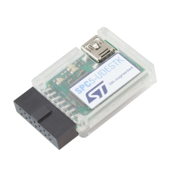
Figure 1. SPC5-UDESTK starter kit version
This document, constituted by two main sections, Getting started and User guide, is related
to an ST dedicate version of PLS commercial debugger product.
The ST version is a starter kit constituted by a software and an hardware component; the
software is a starter version of PLS UDE (Universal Debug Engine) and is defined as
SPC5-UDESTK (starter kit version); its corresponding hardware, the PLS USB/JTAG
adapter, is named SPC5-UDESTK as per the label applied on it.
May 2021
UM1659 Rev 4
1/25
www.st.com
Advertisement
Table of Contents

Related Manuals for ST SPC5-UDESTK


Summary of Contents for ST SPC5-UDESTK
-
Page 1: Figure 1. Spc5-Udestk Starter Kit Version
ST dedicate version of PLS commercial debugger product. The ST version is a starter kit constituted by a software and an hardware component; the software is a starter version of PLS UDE (Universal Debug Engine) and is defined as SPC5-UDESTK (starter kit version);... -
Page 2: Table Of Contents
Installing SPC5-UDESTK ........ - Page 3 UM1659 Contents 3.3.3 FLASH programming ........22 3.3.4 FLASH driver selection .
- Page 4 Figure 4. SPC5-UDESTK PLS USB/JTAG adapter drawing ....... 10 Figure 5.
-
Page 5: Overview And Naming Convention
STMicroelectronics sale’s office. Contact information is available on STMicroelectronics website: http://www.st.com/web/en/support/online_tech_support.html. Feedback The SPC5-UDESTK starter kit version is part of the SPC5 MCU’ s family tool chain based on the ST SPC5 Studio Integrated Development Environment. Regarding any comments about SPC5-UDESTK use the website http://www.st.com/web/en/support/online_tech_support.html... -
Page 6: Getting Started
Discovery board – Discovery+ board – Premium evaluation board The full list of supported boards is available on ST WEB in the Automotive MCUs page in the “Resources Hardware” area which direct URL is: http://www.st.com/stonline/stappl/productcatalog/app?page=partNumberSearchPage&leveli d=FM2098&parentid=1675&resourcetype=HW Power supply for the starter kit board ... -
Page 7: License Registering And Activation Of Spc5-Udestk
The registered version of SPC5-UDESTK unlocks the limitation of code size downloading. STMicroelectronics offers licenses with a validation period of 1 year with option to extend to further 2 years. For the purchase of a license, please visit ST web site and search for SPC5- UDEDEBG or SPC5-UDEDEBG-TL. -
Page 8: Trouble Shooting
Getting started UM1659 Connect the SPC5-UDESTK PLS USB/JTAG adapter for SPC5 to the PC host system using the mini-USB cable. The Windows system will find a new hardware device on your system called "SPC5-UDESTK PLS USB/JTAG adapter for SPC5" in the “Universal serial bus controllers”... -
Page 9: Installing Spc5-Udestk Pls Usb/Jtag Adapter For Spc5
Installing SPC5-UDESTK PLS USB/JTAG adapter for SPC5 The hardware installation of Universal Access Device is done within the following steps: Connect the SPC5-UDESTK PLS USB/JTAG adapter for SPC5 with an USB port of the host PC by the mini-USB cable Plug the SPC5-UDESTK PLS USB/JTAG adapter for SPC5 into the 14-pin JTAG ... -
Page 10: Led Status Indication
Getting started UM1659 Figure 4. SPC5-UDESTK PLS USB/JTAG adapter drawing LED area Mini-USB connector Anti-inversion Pin 1 notch JTAG socket connector to 11 13 target with 10 12 14 anti-inversion notch GAPG0608131426CFT 2.6.6 LED status indication The green LED indicates the target’s IO voltage on the target connector, the yellow LED indicates the target connect state, the red LED indicates the target running state to the user. -
Page 11: User Guide
The SPC5-UDESTK starter kit version can be integrated into the SPC5 Studio as debug plug-in. Beside of this, the SPC5-UDESTK (UDE) starter kit version can be used as stand-alone debug environment. In this context, it is called UDE (Universal Debug Engine). The following chapter shows features of the UDE (Universal Debug Engine) in a stand-alone example. -
Page 12: Figure 5. New Workspace
GAPGCFT0608131431CFT After creating the new workspace, you will be asked to select a target hardware configuration. SPC5-UDESTK (UDE) comes with some default target configurations of starter-kits. Click “Default” button and enable the “Use a default target configuration” to select a predefined configuration. -
Page 13: Loading An Executable
Core::UDEDebugServer: Connection to SPC56EL70 target monitor established: PowerPC Target, JTAG-ID: 0x0AEA9041 When launching SPC5-UDESTK (UDE) for the second time, you may use either File - Open Workspace or File - Recent Workspaces to select the workspace and start a new session with settings from the saved workspace. -
Page 14: Project Management
Mixed Mode entry. 3.2.3 Project management A docked window at the left-hand side of the SPC5-UDESTK (UDE) desktop houses the Explore Symbols tab where the application's source files and their inside procedures are shown after unfolding the markers. -
Page 15: Running And Stepping Through The Application
UM1659 User guide After loading the program code, the Program window shows following content. In the Program window, a yellow arrow indicates the current instruction pointer position. Figure 9. Example of program code GAPG0608131450CFT Warning: After downloading a program executable, the instruction pointer is set to the entry point of the program. -
Page 16: Setting Breakpoints
User guide UM1659 Figure 10. Debug menu GAPG0608131504CFT The icons from the Debug menu are also located in the tool bar covering the same functionality. Short-cuts are available, too. Click now onto the Start Program Execution entry or button and watch the LED on the SPC56-L Discovery kit board flashing the TimeDemo code for UDE. -
Page 17: Cpu Registers
UM1659 User guide Figure 11. Setting breakpoints GAPG0608131506CFT Within the Breakpoint dialog, breakpoints may be added, changed of type and deleted using the corresponding buttons. By clicking on the E/D (Enable/Disable) checkbox, you toggle the breakpoint between active and suspended. Disabled breakpoints are indicated by a red- shaped circle. -
Page 18: Sfr Registers
Warning: Various registers are protected which means that a special unlock sequence is required to change the register value. SPC5-UDESTK (UDE) can unlock these registers. Use the context menu of the register name and disable the entry Write protect. 3.2.8... -
Page 19: Figure 14. Watch Window
Watch tips Furthermore, SPC5-UDESTK (UDE) offers so-called Watch tips, which show you the content of simple variables in the Program window. Highlight i.e. the Buffer[] variable from the main function by a double-click, move the mouse pointer over and the content will be displayed in a watch tip after a short waiting time. -
Page 20: Trigger Functions
User guide UM1659 Figure 15. Watch tips GAPG0608131532CFT Viewing and changing local variables Viewing local variables is provided by the Locals window that can be reached via the menu View - Locals Window. In this window, all currently valid local variables are displayed. The value of the local variable can be changed in the same way as in the Watch window. -
Page 21: Leaving The Project
3.2.10 Leaving the project To leave the current Project select File - Close Workspace from the SPC5-UDESTK (UDE) Desktop menu. The workspace with all settings will be saved automatically. If you want to save the current project under a different project name, select Save Workspace As from File menu. -
Page 22: Enabling The Flash Programming
3.3.2 Enabling the FLASH programming The UDE MemTool is an Add-In of SPC5-UDESTK (UDE) starter kit version and must be activated. This is done via the Add-In Manager, menu Config - Add-in Components. Enable the entry UDE FLASH/OTP Memory Programming Tool. -
Page 23: Flash Driver Selection
Setup and select the driver from the list. Figure 19. FLASH driver selection GAPG0608131546CFT Help and support If this getting started does not help to solve problems in detail, please contact http://www.st.com/web/en/support/online_tech_support.html UM1659 Rev 4 23/25... -
Page 24: Revision History
Table 1. Document revision history Date Revision Changes 08-Aug-2013 Initial release. 17-Sep-2013 Updated Disclaimer. Updated Section 2.1: Before you start, Section 2.5: 01-Dec-2020 License registering and activation of SPC5-UDESTK. Updated Chapter 2.5: License registering and activation 12-May-2021 SPC5-UDESTK. 24/25 UM1659 Rev 4... - Page 25 ST products and/or to this document at any time without notice. Purchasers should obtain the latest relevant information on ST products before placing orders. ST products are sold pursuant to ST’s terms and conditions of sale in place at the time of order acknowledgement.
Need help?
Do you have a question about the SPC5-UDESTK and is the answer not in the manual?
Questions and answers