Table of Contents
Advertisement
Quick Links
UM2789
User manual
SPC58NHADPT386S Rev.C evaluation board
Introduction
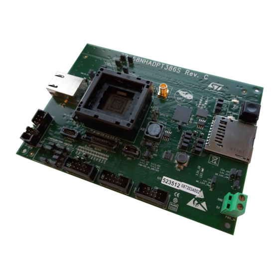
The SPC58NHADPT386S Rev.C evaluation board supports STMicroelectronics SPC58NH92 microcontroller in FPBGA
19x19x1.8 386 package.
Figure 1.
SPC58NHADPT386S Rev.C
Note: picture not contractual
UM2789 - Rev 1 - April 2021
www.st.com
For further information contact your local STMicroelectronics sales office.
Advertisement
Table of Contents

Related Manuals for ST SPC58NHADPT386S Rev.C


Summary of Contents for ST SPC58NHADPT386S Rev.C
-
Page 1: Figure 1. Spc58Nhadpt386S Rev.c
UM2789 User manual SPC58NHADPT386S Rev.C evaluation board Introduction The SPC58NHADPT386S Rev.C evaluation board supports STMicroelectronics SPC58NH92 microcontroller in FPBGA 19x19x1.8 386 package. Figure 1. SPC58NHADPT386S Rev.C Note: picture not contractual UM2789 - Rev 1 - April 2021 www.st.com For further information contact your local STMicroelectronics sales office. -
Page 2: Overview
Overview Overview The SPC58NHADPT386S Rev.C "mini module" is an evaluation board supporting STMicroelectronics SPC58NH92 microcontroller in FPBGA 19x19x1.8 386 package (FPBGA 19x19x1.8 386 3R22+10+2R14+52 PITCH 0.8 BALL 0.55). This "mini module" is designed to be connected onto the SPC58xxMB motherboard, offering a mechanism for easy customer evaluation of the supported devices and to facilitate hardware and software development. -
Page 3: Package Contents
UM2789 Package contents Figure 3. Overview of SPC58NHADPT386S Rev. C "mini module" - bottom Package contents An SPC58NHADPT386S Rev. C adapter package includes the following item: • SPC58NHADPT386S Rev. C "mini module" The MCU is not included, it must be purchased separately. Please contact your sales representative for more details. -
Page 4: License Agreement
Attention: This evaluation board only offers limited features for evaluating ST products. It has not been tested for use with other products and is not suitable for any safety or other commercial or consumer application. This evaluation board is otherwise provided “AS IS”... -
Page 5: Handling Precautions
UM2789 Handling precautions Handling precautions Please take care to handle the package content in order to prevent electrostatic discharge. Before the EVB is used or power is applied, please fully read the following sections on how to correctly configure the board. Failure to correctly configure the board may cause irreparable component, MCU or EVB damage. UM2789 - Rev 1 page 5/36... -
Page 6: Features
UM2789 Hardware description Hardware description Hardware features The SPC58NHADPT386S Rev. C "mini module" board has the following features: • Connector for external power supplies input (5 V) used in stand-alone mode • Reset button with driver and led indicator • Socket for device in FPBGA386 package •... -
Page 7: Power And System Configuration
UM2789 Power and system configuration Power and system configuration Power supplies The "mini module" can be powered by providing voltages or supplied externally by the 2-Way PCB screw connector (CN1) or supplied by the motherboard. When the "mini module" is connected to the motherboard (MB), 1.25 V, 3.3 V and 5.0 V are supplied by MB connector selecting the associated jumpers. - Page 8 UM2789 Power supplies Jumper Description Default Position 5.0V_ADC filtered voltage enable: Figure 9. Overview of Closed SPC58NHADPT386S Rev. C "mini • Closed: connect the 5.0V_EXT to (5.0V_ADC) module" - top - D3 5.0V_ADC trough the filter circuit. VDD_HV_IO_MAIN voltage configuration: Figure 9.
-
Page 9: Jtag/Lfast Lvds/ Sipi Interface Configuration
UM2789 JTAG/LFAST LVDS interface configuration JTAG/LFAST LVDS interface configuration The following jumpers need to configure the JTAG/LFAST LVDS/SIPI: Table 2. JTAG/LFAST/SIPI configuration jumpers Jumper Description Default Position JTAG/LFAST LVDS pin 7 configuration Figure 9. Overview of SPC58NHADPT386S Rev. C "mini •... -
Page 10: System Clock Configuration
UM2789 System clock configuration System clock configuration The mini module supports the usage of crystal clock sources as well as external clock source: Table 3. Clock configuration jumpers Jumper Description Default Position XTAL32 configuration: Figure 9. Overview of SPC58NHADPT386S Open •... -
Page 11: Reset Circuit
UM2789 Reset circuit Reset circuit The "mini module" supports different ways to reset the microcontroller. To use and perform the reset driving there are different jumpers and switches: Table 4. Reset configuration jumpers Jumper Description Default Position Figure 9. Overview of SPC58NHADPT386S Rev. C Reset push button Open "mini module"... -
Page 12: Configuration For Pin Shared
UM2789 Configuration for pin shared between eMMC & SD-card reader Configuration for pin shared between eMMC & SD-card reader The following jumpers need to configure the pin shared between eMMC & SD-CARD READER set the jumpers described in the table below. Table 6. -
Page 13: Hardware Description
UM2789 Hardware description Hardware description 1 Gb/s ethernet interface This paragraph describes the 1Gb/s Ethernet interface present on the "mini module". The Ethernet connector is RJ-45 with integrated magnetics. It shows the functional diagram of the Ethernet interface. Figure 4. 1 Gb/s Ethernet functional diagram Here below the Ethernet ESD protection schema. -
Page 14: Hyperbus Interface
UM2789 Hyperbus interface Hyperbus interface This paragraph describes the hyperbus interface present on the "mini module". The following figure shows the hyperbus scheme. Figure 6. Hyperbus scheme UM2789 - Rev 1 page 14/36... -
Page 15: Emmc Interfacev
UM2789 eMMC interface eMMC interface This paragraph describes the embedded eMMC device present on the "mini module". The figure below shows the functional diagram of the eMMC interface. Figure 7. eMMC functional diagram The following table describes all the hardware of the eMMC interface of the "mini module" and their position on PCB. -
Page 16: Sd/Mmc Interface
This paragraph describes the card reader JEDED/MMC standard version 5.0 compliant. The filter used is EMIF06-MSD02N16 by ST. The SD/MMC card reader needs to use a power switch to limits the output current to a safe level in case the output load exceeds the current limits threshold or a short is present. -
Page 17: Test Points
UM2789 Test points Test points The "mini module" has several test points, described in the table below. Table 10. Test points Test Point Description Position INT_N (on U15) Figure 9. Overview of SPC58NHADPT386S Rev. C "mini module" - top - A2 LDO_O (on U15) Figure 9. -
Page 18: Layout Overview
UM2789 Layout overview Layout overview Figure 9. Overview of SPC58NHADPT386S Rev. C "mini module" - top UM2789 - Rev 1 page 18/36... -
Page 19: Figure 10. Overview Of Spc58Nhadpt386S Rev. C "Mini Module" - Bottom
UM2789 Layout overview Figure 10. Overview of SPC58NHADPT386S Rev. C "mini module" - bottom UM2789 - Rev 1 page 19/36... -
Page 20: Bom
UM2789 Table 12. Item Reference Manufacturer code Value Part description CF1, C1, C2, C6, C8, C18, C19, C20, C25, C28, C34, C37, C39, C42, C45, C48, C98, C105, C113, C114, C115, C116, C117, C118, C119, GCM188R71H104KA57D 100 nF Mult. cer. cap. C120, C121, C124, C125, C126, C128,... - Page 21 UM2789 Item Reference Manufacturer code Value Part description C71, C72, C73, GRM32ER71H475KA88L 4.7 uF Mult. cer. cap. C75, C76, C79, Mult. cer. cap. - not C80, C100, C101, mounted C102, C103 C84, C87 GRM21BR71H474KA88L 470 nF Mult. cer. cap. C1210C226K3RACTU 22 uF Mult.
- Page 22 3.9 uH Inductor MSS1260-563MLD 56uH Inductor L5, L6, L7, L8, L9 BLM21PG221SN1D 220R Multilayerferrite Coax conn female 5 SMA-J-P-H-ST-TH1 SMA-FEM-180 pin, 180° Trans. NPN plastic NJD2873T4G NJD2873T4G power RH1, R1, R2, RH3, R3, R22, R23, R30, R31, R34, R59, R65,...
- Page 23 UM2789 Item Reference Manufacturer code Value Part description Socket FPBGA NP351-386-761 Socket FBGA 386P NP351-386-761 YAMAICHI A6986 A6986 Volt. Reg L5970AD L5970AD Volt. Reg ECS-3953M-080-BN-TR 8MHz Clock Oscillator 74V1G08STR 74V1G08STR CMOS AND Gate SN74AHC125DR SN74AHC125DR Buffer U13, U14 HSP061-4M10Y HSP061-4M10Y ESD Protection Ethernet 1-Port KSZ9031RNXIA...
-
Page 24: Schematic
Schematic Figure 11. uC supply DECOUPLING ARE IMPLEMENTED FOR EVERY POWER PIN 3.3V_ADC 5.0V_ADV 3.3V_S R 5.0V_S R VDD_HV_ADR_S _P VDD_HV_ADV_P VDD_HV_OS C_P 5.0V_EXT 100nF 100nF 10nF 10nF 2.2uF 100nF 10nF 100nF 10nF 2V1P AGND AGND VS S _OS C VDD_HV_FLA_P VDD_LV_P LL MB_3.3V_S R... -
Page 25: Figure 12. Voltage Regulators
Figure 12. Voltage regulators 3.9uH 5.0V_S R 1.2V 22uF 470nF 47uF S GND 1206 P GND P GND R5 1M 470nF FS W RS T 180K S YNCH VBIAS DELAY 430K S S /INH COMP 8.2nF 68nF A6986 390pF 22pF 56uH 5.0V_S R 3.3V... -
Page 26: Figure 13. Uc I/O
Figure 13. uC I/O P E0 P A0 P E0 P E[0] P A[0] P A0 P E1 P A1 P E1 P E[1] P A[1] P A1 P E2 P A2 P E2 P E[2] P A[2] P A2 P E3-CLKOUT P A3 P E3-CLKOUT... -
Page 27: Figure 14. Debug Connectors
Figure 14. Debug connectors JTAG, NEXUS & LFAST CONFIGURATION JUMPERS near DUT pin K21 STRIP3PMD-2MM STRIP3PMD-2MM STRIP3P MD-2MM STRIP3PMD-2MM J 20 J 39 STRIP3P MD-2MM EVTI EVTO ESR0 EVTO CLKOUT PA14-RDY-SIPI_TXN PK10-EVTI PA8-TDI PJ 3-EVTO PC1-ESR0 EVTO/ESR0 PE3-CLKOUT PA9-TDO PK10 PJ 3 ESR0 STRIP 3P MD-2MM... -
Page 28: Figure 15. Clock And Reset
Figure 15. Clock and reset 32kHz Oscillator External Oscillator External Clock Input J 25 EVB_EXTAL 3.3V_SR C105 100nF J 27 EXTAL STRIP2PMD-2MM STRIP3PMD-2MM C106 10pF Note - External 3.3V regulator MUST be VSS_OSC J 26 8MHz enabled when using Note - Internal 40MHz oscillator module Pull-Up on Pin 1... -
Page 29: Figure 16. Ethernet Interface
Figure 16. Ethernet interface Pull up Supply Filters DVDDH DVDDH DVDDH DVDDH TRCT1 TRCT2 TRCT3 TRCT4 PIN1 PIN12 PIN47 PIN4 PIN9 3.3V_S R AVDDH 1.2V_S R AVDDL C113 C114 C115 C116 C123 C124 C125 C126 C131 C132 C133 100nF 100nF 100nF 100nF 47uF... -
Page 30: Figure 17. Emmc And Sd Card
Figure 17. eMMC and SD card HYPERBUS SD-CARD READER 3.3V_SR 3.3V_SDMMC P F9_MB OUT1 PN11 RSTO# OUT2 CS 2 CS2# PP 9 OUT3 PORST RESET# C117 C118 TP 4 FAULT S71KL256SC0BHB000 100nF 100nF 3.3V_SR INT# VCCQ STMPS2151MTR PN12 PP 14 PN10 PN12_MB CLOSE TO U17... -
Page 31: Figure 18. Motherboard Connectors
Figure 18. Motherboard connectors CN9A CN9B CN8A CN8B MB_5.0V_LR MB_5.0V_LR MB_5.0V_LR MB_5.0V_LR SH16 MB_1.25V_SR MB_1.25V_SR MB_5.0V_LR MB_5.0V_LR MB_5.0V_LR MB_5.0V_LR MB_1.25V_SR MB_1.25V_SR MB_5.0V_LR MB_5.0V_LR MB_5.0V_LR MB_1.25V_SR MB_1.25V_SR MB_5.0V_LR MB_5.0V_LR SH15 MB_1.25V_SR MB_1.25V_SR MB_5.0V_LR SH14 SH13 SH12 SH11 SH10 PM10 PM11 PM10 PM11 PA10 PA11... -
Page 32: Revision History
UM2789 Revision history Table 13. Document revision history Date Version Changes 20-Apr-2021 Initial release. UM2789 - Rev 1 page 32/36... -
Page 33: Table Of Contents
UM2789 Contents Contents Overview ................2 Package Contents. - Page 34 UM2789 List of tables List of tables Table 1. Power configuration jumpers ............7 Table 2.
- Page 35 SPC58NHADPT386S Rev.C........
- Page 36 ST’s terms and conditions of sale in place at the time of order acknowledgement. Purchasers are solely responsible for the choice, selection, and use of ST products and ST assumes no liability for application assistance or the design of Purchasers’...
Need help?
Do you have a question about the SPC58NHADPT386S Rev.C and is the answer not in the manual?
Questions and answers