Table of Contents
Advertisement
Quick Links
UM2640
User manual
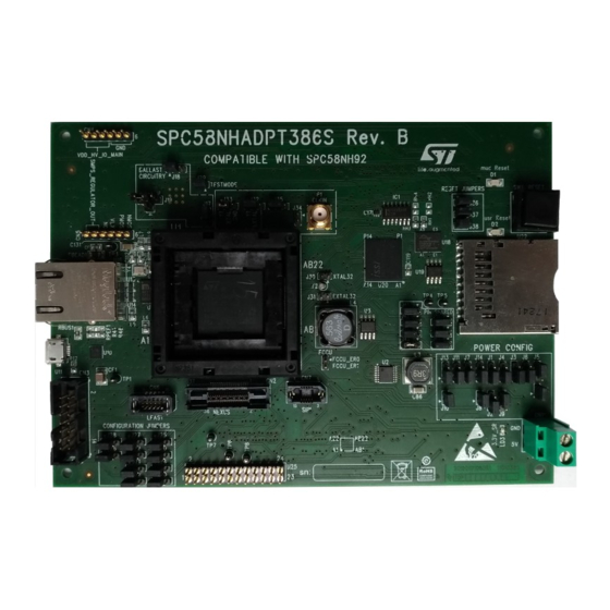
SPC58NHADPT386S Rev.B evaluation board
Introduction
The SPC58NHADPT386S Rev.B evaluation board supports STMicroelectronics SPC58NH92 microcontroller in FPBGA
19x19x1.8 386.
Figure 1.
SR6-EVB000 Rev. B
Note: picture is not contractual.
UM2640 - Rev 1 - July 2020
www.st.com
For further information contact your local STMicroelectronics sales office.
Advertisement
Table of Contents

Subscribe to Our Youtube Channel
Related Manuals for ST SPC58NHADPT386S


Summary of Contents for ST SPC58NHADPT386S
-
Page 1: Figure 1. Sr6-Evb000 Rev. B
UM2640 User manual SPC58NHADPT386S Rev.B evaluation board Introduction The SPC58NHADPT386S Rev.B evaluation board supports STMicroelectronics SPC58NH92 microcontroller in FPBGA 19x19x1.8 386. Figure 1. SR6-EVB000 Rev. B Note: picture is not contractual. UM2640 - Rev 1 - July 2020 www.st.com For further information contact your local STMicroelectronics sales office. -
Page 2: Overview
SPC58NHADPT386S Rev. B mini module The MCU is not included, it must be purchased separately. Please contact your sales representative for more details. Supported devices The SPC58NHADPT386S Rev. B mini module supports the following STMicroelectronics family of microcontrollers in FBGA 19x19x1.8 386: • SPC58NH92C5xx... -
Page 3: License Agreement
Attention: This evaluation board only offers limited features for evaluating ST products. It has not been tested for use with other products and is not suitable for any safety or other commercial or consumer application. This evaluation board is otherwise provided “AS IS”... -
Page 4: Handling Precautions
UM2640 Handling precautions Handling precautions Please take care to handle the package contents in a manner such as to prevent electrostatic discharge. Before the EVB is used or power is applied, please fully read the following sections on how to correctly configure the board. -
Page 5: Features
UM2640 Hardware description Hardware description Hardware features The SPC58NHADPT386S Rev. B mini module board has the following features: • Connector for external power supplies input (5 V) used in stand-alone mode • Reset button with driver and led indicator •... -
Page 6: Hardware Dimension
The mini module has the following dimension: • PCB area: 157 mm x 114.3 mm • Top components height: 19 mm max • Bottom components height: 3.5 mm max Figure 2. SPC58NHADPT386S Rev. B top component view UM2640 - Rev 1 page 6/37... -
Page 7: Power And System Configuration
In this setup, the external power supply input available on the mini module should NOT be used. When the SPC58NHADPT386S Rev. B mini module is used as a stand-alone board, 5V0 voltages must be supplied externally, 3V3 and 1V2 voltages will be generated internally by specific circuit on the mini-module. - Page 8 UM2640 Power supplies Jumper Description Default Position Closed VDD_HV_IO_ETH1 voltage enable: Figure 10. Overview of SPC58NHADPT386S Rev. B mini • Closed: connect 3.3V_SR to (Connect 3.3V_SR to module - top - D4 VDD_HV_IO_ETH1 pins VDD_HV_IO_ETH1 pins) VDD_HV_IO_ETH0 voltage configuration: Figure 10. Overview of •...
-
Page 9: Jtag/Lfast Lvds/ Sipi Interface Configuration
The following jumpers need to configure the JTAG/LFAST LVDS/SIPI: Table 2. JTAG/LFAST/SIPI configuration jumpers Jumper Description Default Position JTAG/LFAST LVDS pin 7 configuration Figure 10. Overview of SPC58NHADPT386S Rev. B mini • 1-2: EVTI module - top - A4 (EVTI) • 2-3: PK10 SIPI pin 3 configuration Figure 10. -
Page 10: System Clock Configuration
The mini module supports the usage of crystal clock sources as well as external clock source: Table 3. Clock configuration jumpers Jumper Description Default Position XTAL32 configuration Figure 10. Overview of SPC58NHADPT386S Open • Close: connect pin 2 of 32.768KHz crystal Rev. B mini module - top - C2 (Y2) to XTAL32 EXTAL32 configuration Figure 10. -
Page 11: Reset Circuit
Table 5. Pin shared between eMMC & SD card reader Jumper Jumper Description Default Position PQ4 configuration Figure 10. Overview of SPC58NHADPT386S Rev. B mini module - top • 1-2 PQ4_S (SD-CARD) - D3 (SD-CARD) • 2-3 PQ4_E (eMMC) PQ5 configuration Figure 10. -
Page 12: Hardware Description
1 Gb/s Ethernet interface Symbol Description Position ESD Protection Figure 10. Overview of SPC58NHADPT386S Rev. B mini module - top - A2 ESD Protection Figure 10. Overview of SPC58NHADPT386S Rev. B mini module - top - A2 Ethernet 1-Port GigabitEthrnt Ethernet Figure 10. -
Page 13: Hyperbus Interface
Hyperbus interface This paragraph describes the Hyperbus interface present on the mini module. The SPC58NHADPT386S contains only one CS (CNS), instead the memory device contains two CSs lines, one for RAM and one for FLASH. The second CS is emulated using one GPIO signal (GPIO84 – PF[4]). -
Page 14: Usb Port
UM2640 USB Port USB Port This paragraph describes the USB interface present on the mini-module. The USB transceiver used is the STULPI01 high-speed USB 2.0 transceiver. The USB connector is mini-USB. Figure 6. USB functional diagram shows the functional diagram of the USB interface. Figure 6. -
Page 15: Emmc Interfacev
Table 9. USB Port Symbol Description Position Transceiver Figure 10. Overview of SPC58NHADPT386S Rev. B mini module - top - A3 Connector Micro USB 5 Pin Figure 10. Overview of SPC58NHADPT386S Rev. B mini module - top - A3 Oscillator Figure 11. -
Page 16: Sd/Mmc Interface
SD/MMC interface Symbol Description Position CMOS Switch Figure 10. Overview of SPC58NHADPT386S Rev. B mini module - top - D2 Filter EMI 6-line Micro Figure 11. Overview of SPC58NHADPT386S Rev. B mini module - bottom - A2 Connector SD reverse push-push Figure 10. -
Page 17: Test Points
Test points Test Point Description Position PSWN (on U10) Figure 10. Overview of SPC58NHADPT386S Rev. B mini module - top - A3 INT_N (on U15) Figure 10. Overview of SPC58NHADPT386S Rev. B mini module - top - A2 LDO_O (on U15) Figure 10. - Page 18 UM2640 Connectors Figure 10. Overview of SPC58NHADPT386S Rev. B mini module - top UM2640 - Rev 1 page 18/37...
-
Page 19: Figure 11. Overview Of Spc58Nhadpt386S Rev. B Mini Module - Bottom
UM2640 Connectors Figure 11. Overview of SPC58NHADPT386S Rev. B mini module - bottom UM2640 - Rev 1 page 19/37... -
Page 20: Bom
UM2640 Table 14. Ref. Value Description Manufacturer Manufcode designator C1, C2, C6, C8, C18, C19, C20, C25, C28, C34 ,C37, C39, C42, C45, C48, C98, C99, C105, C113, C114, C115, C116, C117, C118, C119, C120, C121, 100 nF Mult.cer. cap. Murata GCM188R71H104KA57D C124, C118,... - Page 21 UM2640 Ref. Value Description Manufacturer Manufcode designator C5, C14, C50, C53, C56, C59, 2.2 uF Mult. cer. cap. Murata GCM21BR71C225KA64L C62, C65, C68, C77, C78, C81 C15, C51, C54, C57, C60, C63, 47 nF Mult. cer. cap. Murata GCM188R71H473KA55D C66, C69, C82 C17, C22, C23, C24, C27, C31, 4.7 uF...
- Page 22 Inductor Coilcraft MSS1260-563MLD L5, L6, L7, L8, 220R Multilayer ferrite Murata BLM21PG221SN1D Coax conn female 5 pin, SMA-FEM-180 Samtec SMA-J-P-H-ST-TH1 180° Trans. NPN plastic NJD2873T4G ON Semiconductor NJD2873T4G power RH1, R1, R2, RH3, R3, R12, R22, R23, R30, Resistor Neohm...
- Page 23 UM2640 Ref. Value Description Manufacturer Manufcode designator R57, R64 Resistor Neohm Resistor Pushbutton NO B6110-0 Pushbutton Delta Elettronica B6110-0 (N5) TP1, TP2, TP3, PCB test point 1 pin - TP4, TP5, TP6, TESTPOINT Black TP7, TP8 Socket FPBGA 386P Socket FBGA NP351-386-761 Yamaichi NP351-386-761...
-
Page 24: Schematic
Schematic Figure 12. uC supply DECOUPLI NG ARE I M PLEM ENTED FOR EVERY POW ER PI N 3.3V_ADC 5.0V_ADV 3.3V_S R 5.0V_S R VDD_HV_ADR_S _P VDD_HV_ADV_P VDD_HV_OS C_P 5.0V_EXT 100nF 100nF 10nF 10nF 2.2uF 100nF 10nF 100nF 10nF 2V1P AGND AGND VS S _OS C... -
Page 25: Figure 13. Voltage Regulators
Figure 13. Voltage regulators 3.9uH 5.0V_S R 1.2V 22uF 470nF 47uF S GND 1206 P GND P GND R5 1M 470nF FS W RS T 180K S YNCH VBIAS DELAY S S /INH COMP 430K 8.2nF 68nF A6986 390pF 22pF 56uH 5.0V_S R 3.3V... -
Page 26: Figure 14. Uc - Gpio
Figure 14. uC - GPIO P E0 P A0 P E0 P A0 PE[0] PA[0] P E1 P A1 P E1 P A1 PE[1] PA[1] P E2 P A2 P E2 P A2 PE[2] PA[2] P E3-CLKOUT P A3 P E3-CLKOUT P A3 PE[3] PA[3]... -
Page 27: Figure 15. Debug Connectors
Figure 15. Debug connectors J TAG, NEXUS & LFAST CONFIGURATION J UMP ERS J 26 STRIP3PMD-2MM STRIP3PMD-2MM STRIP3PMD-2MM STRIP3PMD-2MM STRIP3PMD-2MM J 52 STRIP3PMD-2MM EVTI EVTO ESR0 EVTO CLKOUT PK10-EVTI PA14-RDY-S IPI_TXN PA8-TDI PJ 3-EVTO PC1-ESR0 EVTO/ESR0 PE3-CLKOUT PA9-TDO PK10 PA14 PJ 3 ESR0 J 20... -
Page 28: Figure 16. Oscillators And Reset
Figure 16. Oscillators and reset 32kHz Os c i l l a t or Ext e r na l Os c i l l a t or Ext e r na l Cl oc k I nput J 32 EVB_EXTAL 3.3V_SR C105 100nF J 34... -
Page 29: Figure 17. Usb Interface
Figure 17. USB interface 3.3V_S R CLOSE TO U1 0 PI N F5 3.3V_S R 3.3V_S R US B_XI 26MHZ VS S _OS C 4.7uF VBUS VBUS DM_U DP _U US B_ID CF3 1uF50V 3.3V_S R VDVIO VBAT ECMF02-4CMX8 CF4 1uF 50V US B_XI VDVIO VDVIO... -
Page 30: Figure 18. Ethernet Interface
Figure 18. Ethernet interface Pul l up Suppl y Fi l t e r s 3.3V_S R 3.3V_S R 3.3V_S R 3.3V_S R TRCT1 TRCT2 TRCT3 TRCT4 PI N1 PI N12 PI N47 PI N4 PI N9 3.3V_S R AVDDH 1.2V_S R AVDDL C113... -
Page 31: Figure 19. Hyperbus, Emmc And Sd Card Reader
Figure 19. Hyperbus, eMMC and SD card reader HYPERBUS SD- CARD READER 3.3V_SR 3.3V_SR 3.3V_SR 3.3V_SDMMC U17A IC1A OUT1 PN11 RSTO# OUT2 PF4_MB NC7WZU04P6X CS2# OUT3 CD74AC32M PORST C117 C118 RESET# FAULT S71KL256SC0BHB000 100nF 100nF 3.3V_SR INT# VCCQ STMPS2151MTR IC1B PP14 PN10 PN12... -
Page 32: Figure 20. Motherboard Connectors
Figure 20. Motherboard connectors CN9A CN9B CN8A CN8B MB_5.0V_LR MB_5.0V_LR MB_5.0V_LR MB_5.0V_LR SH16 MB_1.25V_S R MB_1.25V_S R MB_5.0V_LR MB_5.0V_LR MB_5.0V_LR MB_5.0V_LR MB_1.25V_S R MB_1.25V_S R MB_5.0V_LR MB_5.0V_LR MB_5.0V_LR MB_1.25V_S R MB_1.25V_S R MB_5.0V_LR MB_5.0V_LR SH15 MB_1.25V_S R MB_1.25V_S R MB_5.0V_LR SH14 SH13 SH12... -
Page 33: Revision History
UM2640 Revision history Table 15. Document revision history Date Version Changes 21-Jul-2020 Initial release. UM2640 - Rev 1 page 33/37... -
Page 34: Table Of Contents
UM2640 Contents Contents Overview ................2 Package Contents. - Page 35 UM2640 List of tables List of tables Table 1. Power configuration jumpers ............7 Table 2.
- Page 36 Overview of SPC58NHADPT386S Rev. B mini module - bottom ....... .
- Page 37 ST’s terms and conditions of sale in place at the time of order acknowledgement. Purchasers are solely responsible for the choice, selection, and use of ST products and ST assumes no liability for application assistance or the design of Purchasers’...
Need help?
Do you have a question about the SPC58NHADPT386S and is the answer not in the manual?
Questions and answers