Table of Contents
Advertisement
Quick Links
UM2723
User manual
SPC58XXADPT176S Rev.B evaluation board
Introduction
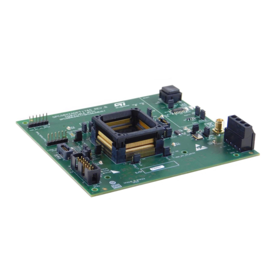
The SPC58XXADPT176S Rev.B evaluation board supports STMicroelectronics SPC58EE84E7, SPC58NE84E7,
SPC58XN8XE7 and SP58xG8xE7 microcontroller in LQFP 176 24x24x1.4 package with exposed pad down.
Figure 1.
SPC58XXADPT176S Rev. B
UM2723 - Rev 1 - June 2020
www.st.com
For further information contact your local STMicroelectronics sales office.
Advertisement
Table of Contents

Related Manuals for ST SPC58XXADPT176S


Summary of Contents for ST SPC58XXADPT176S
- Page 1 UM2723 User manual SPC58XXADPT176S Rev.B evaluation board Introduction The SPC58XXADPT176S Rev.B evaluation board supports STMicroelectronics SPC58EE84E7, SPC58NE84E7, SPC58XN8XE7 and SP58xG8xE7 microcontroller in LQFP 176 24x24x1.4 package with exposed pad down. Figure 1. SPC58XXADPT176S Rev. B UM2723 - Rev 1 - June 2020 www.st.com...
-
Page 2: Overview
UM2723 Overview Overview The SPC58XXADPT176S Rev. B mini module is an evaluation board supporting STMicroelectronics SPC58EE84L7, SPC58NE84E7, SPC58XN8XE7 and SP58xG8xE7 microcontrollers in LQFP 176 24x24x1.4 package with exposed pad down. This mini module is designed to be connected onto the SPC58XXMB motherboard, offering a mechanism for easy customer evaluation of the supported devices, and to facilitate hardware and software development. -
Page 3: License Agreement
Attention: This evaluation board only offers limited features for evaluating ST products. It has not been tested for use with other products and is not suitable for any safety or other commercial or consumer application. This evaluation board is otherwise provided “AS IS”... -
Page 4: Handling Precautions
UM2723 Handling precautions Handling precautions Please take care to handle the package contents in a manner such as to prevent electrostatic discharge. Before the EVB is used or power is applied, please fully read the following sections on how to correctly configure the board. -
Page 5: Hardware Description
UM2723 Hardware description Hardware description Hardware features The SPC58XXADPT176S Rev. B mini module board has the following features: • Connector for external power supplies input (5 V, 3.3 V, 1.25 V) used in stand-alone mode • Reset button with driver and led indicator •... -
Page 6: Hardware Dimension
PCB area: 127 mm x 114.3 mm • Top components height: 19 mm max • Bottom components height: 3.5 mm max • PCB thickness: 1.6 mm Figure 2. SPC58XXADPT176S Rev. B top component view UM2723 - Rev 1 page 6/28... -
Page 7: Power And System Configuration
NOT be used. When the SPC58XXADPT176S Rev. B mini module is used as a stand-alone board, external power supplies must be used (5 V, 3.3 V, 1.25 V). -
Page 8: Jtag/Lfast Lvds/ Sipi Interface Configuration
UM2723 JTAG/LFAST LVDS interface configuration JTAG/LFAST LVDS interface configuration The following jumpers need to configure the JTAG/LFAST LVDS: Table 2. LFAST configuration jumpers Jumper Description Default JTAG/LFAST LVDS pin 9 configuration • 1-2: EVTO (EVTO) • 2-3: ESR0 JTAG/LFAST LVDS pin 10 configuration •... -
Page 9: Reset Circuit
UM2723 Reset circuit Reset circuit The mini module supports different ways to reset the microcontroller. To use and perform the reset driving there are different jumpers and switches: Table 4. Reset configuration jumpers Jumper Description Default Reset push button Open Connect the external reset to the reset driver for ESR0 and PORST pins Close Connect the external reset to ESR0 pin... -
Page 10: Configuration For Spc58Ee84E7/Spc58Ne84E7
UM2723 Configuration for SPC58EE84E7/SPC58NE84E7 Configuration for SPC58EE84E7/SPC58NE84E7 To configure the board for SPC58EE84E7/SPC58NE84E7 set the jumpers described in the table below. Table 7. SPC58EE84E7/SPC58NE84E7 configuration jumpers Jumper Description Default Device pin 10 port configuration 1-2 PL8 (PL 8) 2-3 VDD_LV_BD Device pin 154 function configuration Closed •... -
Page 11: Configuration For Spc58Xn8Xe7 Ed
UM2723 Configuration for SPC58XN8XE7 ED Configuration for SPC58XN8XE7 ED To configure the board for SPC58XN8XE7 set the jumpers described in the table below. Table 9. SPC58XN8XE7 ED configuration jumpers Jumper Description Configuration Device pin 10 port configuration 1-2 PL8 (VDD_LV_BD) 2-3 VDD_LV_BD Device pin 154 function configuration Open... -
Page 12: Hardware Description
The following table describes all the jumpers of the mini module, their default configuration and their position on PCB. Table 11. Jumpers Jumper Description Default Position VDD_HV_ADR voltage configuration: • 1-2 5.0V_LR Figure 1. SPC58XXADPT176S Rev. B - C2 (5.0V_LR) • 2-3 3.3V_SR VDD_HV_ADV voltage configuration: • 1-2 5.0V_LR Figure 1. SPC58XXADPT176S Rev. B - C2 (5.0V_LR) •... - Page 13 UM2723 Jumpers Jumper Description Default Position PH[11]/EVTO connection to QSH motherboard Not mounted Figure 1. SPC58XXADPT176S Rev. B - A2 connectors Device pin 153 EXTREG_SEL function configuration: • 2-1 Reserved for ST Figure 1. SPC58XXADPT176S Rev. B - B2 •...
-
Page 14: Test Points
Test point Description Position GT1, GT2, GT3, GT4, GT5 GND test point VSS_OSC test point Figure 1. SPC58XXADPT176S Rev. B - D3 AGND test point Figure 1. SPC58XXADPT176S Rev. B - D3 JCOMP_RxDATA_N test point Figure 1. SPC58XXADPT176S Rev. B... -
Page 15: Connectors
2 X Samtec QSH series, 240 way connector to connect mini module to Motherboard External power supplies input (5 V, 3.3 V, 1.25 V) SMA connector for external clock Input Figure 3. Overview of SPC58XXADPT176S Rev. B mini module - top UM2723 - Rev 1 page 15/28... -
Page 16: Figure 4. Overview Of Spc58Xxadpt176S Rev. B Mini Module - Bottom
UM2723 Connectors Figure 4. Overview of SPC58XXADPT176S Rev. B mini module - bottom UM2723 - Rev 1 page 16/28... -
Page 17: Bom
UM2723 Table 14. Ref. Value Description Manufacturer Manufcode designator Samtec Conn TFM 10 pin, Samtec TFM-105-02-L-D-WT with weld Tabs TFM-105-02-L-D-WT C1, C3, C5, C7, C10, C16, C18, 100 nF Mult. cer. cap. C20, C22, C24, C58, C103, C122 C2, C4, C6, C8, C11, C17, C19, C21, C23, C25,... - Page 18 Strip mamle 20 pin, 1 row , 180° J38, J40 STRIP3+1PMD-2MM Harwin M22-2512005 see match parts Coax conn female 5 pin, SMA-FEM-180 Samtec SMA-J-P-H-ST-TH1 180° NJD2873T4G Trans. NPN plastic pow er ON Semiconductor NJD2873T4G R1, R2, R7, R15, R18, Resistor R19, R21,...
- Page 19 HCMOS buffer STMicroelectronics 74LVC125AMTR 74V1G08STR CMOS AND gate STMicroelectronics 74V1G08STR 40 MHz Quartz NX5032GA SPC58xxADPT176S EVB for SPC58EE84E7/ SPC58NE84E7 eTQFP176(A0A4) J1, J2, J3, J4, J6, J7, J21, J23, J24, J39, J41, J44, J22, Bridge 2 pins female 2 mm Harwin...
-
Page 20: Schematic
PD[12] PC13 PD13 PC[13] PD[13] PC14 PD14 TP13 PC[14] PD[14] PC15 PD15 PC[15] PD[15] PF[0..15] (pg5,6) (pg6) PE[0..15] SPC58xxADPT176S LQFP 176 24x24x1.4 SIPI_RXP SIPI_RXP (pg4) PE[0] PF[0] PE[1] SIGNALS PF[1] PE[2] PF[2] PE[3] PF[3] PE[4] PF[4] PE[5] PF[5] PE[6] PF[6]... -
Page 21: Figure 6. Jtag, Jtag/Lfast Lvds Interface, Sipi I/F And Smps Interface Conn
Figure 6. JTAG, JTAG/LFAST LVDS interface, SIPI I/F and SMPS interface CONN JTAG interface JTAG/LFAST LVDS INTERFACE 10 Pin Version Place CAPS as close to VDD_HV_IO_JTAG VDD_HV_IO_JTAG VDD_HV_IO_JTAG connector pins as possible but do NOT fit caps at board assembly. VDD_HV_IO_JTAG JCOMP C132... -
Page 22: Figure 7. Clock And Reset Circuitry
Figure 7. Clock and reset circuitry External Oscillator External Clock Input EVB-EXTAL EVB-EXTAL 3.3V_SR EXTAL 100nF EXTAL(pg3) (MCU Crystal Input) STRIP2PMD-2MM-O STRIP3PMD-2MM Note - External 3.3V 8MHz regulator MUST be 40MHz enabled when using Note - Internal oscillator module Pull-Up on Pin 1 XTAL XTAL(pg3) R7 0R... -
Page 23: Figure 8. Daughter Card To Motherboard Connector
Figure 8. Daughter card to motherboard connector PortA PortB PortC PortD PortE PortF PortG PortH PortI PortJ PA[0..15] PB[0..15] PC[0..15] PD[0..15] PE[0..15] PF[0..15] PG[0..15] PH[0..15] PI[0..15] PJ[0..4] (pg4) PA[0..15] (pg4) PB[0..15] (pg4) PC[0..15] (pg4) PD[0..15] (pg4) PE[0..15] (pg4,6) PF[0..15] (pg4) PG[0..15] (pg4) PH[0..15]... -
Page 24: Revision History
UM2723 Revision history Table 15. Document revision history Date Version Changes 16-Jun-2020 Initial release. UM2723 - Rev 1 page 24/28... -
Page 25: Table Of Contents
UM2723 Contents Contents Overview ................2 Package Contents. - Page 26 UM2723 List of tables List of tables Table 1. Power configuration jumpers ............7 Table 2.
- Page 27 Overview of SPC58XXADPT176S Rev. B mini module - bottom ....... .
- Page 28 ST’s terms and conditions of sale in place at the time of order acknowledgement. Purchasers are solely responsible for the choice, selection, and use of ST products and ST assumes no liability for application assistance or the design of Purchasers’...
Need help?
Do you have a question about the SPC58XXADPT176S and is the answer not in the manual?
Questions and answers