Table of Contents
Advertisement
Quick Links
UM2764
User manual
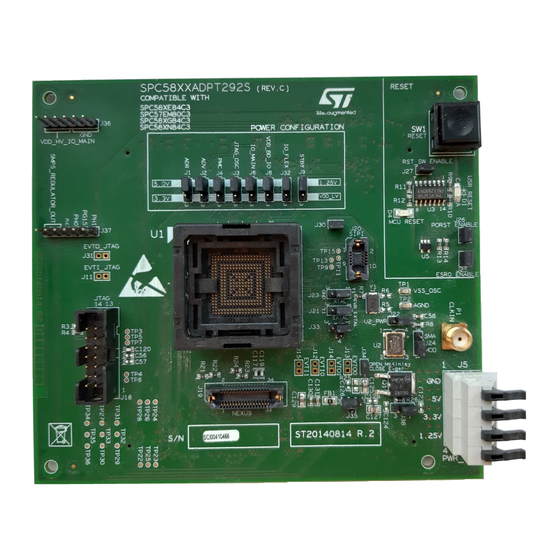
SPC58XXADPT292S Rev. C evaluation board
Introduction
The evaluation board SPC58XXADPT292S Rev. C "mini module" supports STMicroelectronics SPC58XE84C3,
SPC57EM80C3, SPC58XG84C3 and SPC58XN84C3 microcontrollers in FPBGA292 package.
Figure 1.
SPC58XXADPT292S Rev. C
Note: picture is not contractual.
UM2764 - Rev 1 - January 2021
www.st.com
For further information contact your local STMicroelectronics sales office.
Advertisement
Table of Contents

Related Manuals for ST SPC58XXADPT292S


Summary of Contents for ST SPC58XXADPT292S
- Page 1 UM2764 User manual SPC58XXADPT292S Rev. C evaluation board Introduction The evaluation board SPC58XXADPT292S Rev. C "mini module" supports STMicroelectronics SPC58XE84C3, SPC57EM80C3, SPC58XG84C3 and SPC58XN84C3 microcontrollers in FPBGA292 package. Figure 1. SPC58XXADPT292S Rev. C Note: picture is not contractual. UM2764 - Rev 1 - January 2021 www.st.com...
-
Page 2: Overview
The "mini module" may be used as a stand-alone unit allowing access to the CPU, but no access to the I/O pins as any motherboard peripherals. Figure 2. Overview of SPC58XXADPT292S Rev. C "mini module" - top UM2764 - Rev 1 page 2/26... -
Page 3: Package Contents
Package contents Figure 3. Overview of SPC58XXADPT292S Rev. C "mini module" - bottom Package contents An SPC58XXADPT292S Rev. C adapter package includes the following item: • SPC58XXADPT292S Rev. C "mini module" Supported devices The "mini module" supports the following STMicroelectronics family of microcontrollers in FPBGA292 package: •... -
Page 4: License Agreement
Attention: This evaluation board only offers limited features for evaluating ST products. It has not been tested for use with other products and is not suitable for any safety or other commercial or consumer application. This evaluation board is otherwise provided “AS IS”... -
Page 5: Handling Precautions
UM2764 Handling precautions Handling precautions Please take care to handle the package contents in a manner such as to prevent electrostatic discharge. Before the EVB is used or power is applied, please fully read the following sections on how to correctly configure the board. -
Page 6: Features
UM2764 Hardware description Hardware description Hardware features The "mini module" has the following features: • Connector for external power supplies input (5 V, 3.3 V, 1.25 V) used in stand-alone mode. • Reset button with driver and led indicator • Socket for device in FPBGA292 package with exposed pad down •... -
Page 7: Power And System Configuration
Table 1. Power configuration jumpers Jumper Description Default Position VDD_HV_ADR voltage configuration Figure 4. SPC58XXADPT292S Rev. C top "mini 1-2 (5.0V_LR) from 5.0V_LR or 3.3V_SR module" view - B2 VDD_HV_ADV voltage configuration Figure 4. SPC58XXADPT292S Rev. C top "mini 1-2 (5.0V_LR) from 5.0V_LR or 3.3V_SR... -
Page 8: Microcolntroller Configuration
SPC57EM80C3. Table 2. Microcontroller SPC57EM80C3 configuration related jumpers Jumper Description Default Position Device ball T11 VDDSTBY Figure 4. SPC58XXADPT292S Rev. C top "mini (Connect VDDSTBY with function configuration module" view - C3 3.3_SR) Open Device ball N19 NC Figure 4. SPC58XXADPT292S Rev. C top "mini function configuration module"... -
Page 9: Port Configuration
Ports related jumpers Jumper Description Default Position TESTMODE settings Close Figure 4. SPC58XXADPT292S Rev. C top "mini module" view - C2 PF[15]/EVTI connection to QSH Open Figure 4. SPC58XXADPT292S Rev. C top "mini module" view - A2 motherboard connectors PH[11]/EVTO connection to QSH Open Figure 4. -
Page 10: System Clock Configuration
Table 6. Reset configuration jumpers Jumper Description Default Position Figure 4. SPC58XXADPT292S Rev. C top "mini module" view Reset push button Open Connect the external reset to the reset Figure 4. SPC58XXADPT292S Rev. C top "mini module" view driver for... -
Page 11: Test Points
Table 7. Test points Test Point Description Position VSS_OSC test point Figure 4. SPC58XXADPT292S Rev. C top "mini module" view - D3 AGND test point Figure 4. SPC58XXADPT292S Rev. C top "mini module" view - D3 JCOMP test point Figure 4. SPC58XXADPT292S Rev. C top "mini module" view... -
Page 12: Connectors
Table 8. Other connectors Connectors Description Position 10-pin header connector for SIPI Figure 4. SPC58XXADPT292S Rev. C top "mini module" view - C2 interface 14-pin header connector for JTAG port Figure 4. SPC58XXADPT292S Rev. C top "mini module" view - A4 34-pin SAMTEC connector for Nexus 2 Figure 4. -
Page 13: Layout Overview
UM2764 Layout overview Layout overview Figure 4. SPC58XXADPT292S Rev. C top "mini module" view UM2764 - Rev 1 page 13/26... -
Page 14: Figure 5. Spc58Xxadpt292S Rev. C Bottom "Mini Module" View
UM2764 Layout overview Figure 5. SPC58XXADPT292S Rev. C bottom "mini module" view UM2764 - Rev 1 page 14/26... -
Page 15: Bom
UM2764 Table 9. Item Qty Reference Manufacturer code Value Part description C1, C3, C5, C7, C10, C12, C16, C18, C20, 100 nF Mult. cer. cap. 50V 0603 C22, C24 ,C26, C28, C30, C58, C59 C2, C4, C6, C8, C11, C13, C17, C19 ,C21, C23, C25, C27, C29, 10 nF Mult. - Page 16 UM2764 Item Qty Reference Manufacturer code Value Part description NJD2873 NPN plastic power transistor DPAK R1, R2, R7, R20, R21, Resistor 1/10W 1% 0603 R22, R23, R24, R26 Resistor 1/10W 1% 0603 - do not mount R4, R9 Resistor 1/10W 1% 0603 R5, R6 Resistor 1/10W 1% 0603 - Do not mount! 100R...
-
Page 17: Schematics
Schematics Figure 6. Microcontroller power 5.0V_LR 3.3V_SR 5.0V_SR 1.25V_SR VDD_HV_ADR 100nF 10nF 100nF 10nF AGND AGND C121 100nF 10nF 2.2uF VDD_HV_ADV VDD_HV_IO_JTAG AGND VDD_HV_JTAG_OSC 100nF 10nF AST0250404 VSS_OSC VDD_HV_PMC C118 2.2uF 100nF 10nF 100nF 10nF 5.0V_SR VDD_HV_IO_MAIN 3.3V_SR 1.25V_SR VDD_HV_IO_MAIN 4.7uF 4.7uF 100nF... -
Page 18: Figure 7. Microcontroller I/O
Figure 7. Microcontroller I/O SOCKET (pg5 ) PA[0..15] PB[0..15] (pg5 ) PA[0] PB[0] PA[1] PB[1] PA[2] PB[2] differential signals PA[3] PB[3] PA[4]/ES R1 PB[4] JCOMP (pg6 ) JCOMP PA[5] PB[5] PA[6]/TCK PB[6] PA[7]/TMS PB[7] PA[8]/TDI PB[8] PA[9]/TDO PB[9] PA10 PB10 PA[10] PB[10] PA11... -
Page 19: Figure 8. Board Connector
Figure 8. Board connector PortA PortB PortC PortD PortE PortF PortG PortH PortI PortJ PortK PortL PA[0..15] PB[0..15] PC[0..15] PD[0..15] PE[0..15] PF[0..15] PG[0..15] PH[0..15] PI[0..15] PJ[0..15] PK[0..15] PL[0..15] (pg4) PA[0..15] (pg4) PB[0..15] (pg4) PC[0..15] (pg4) PD[0..15] (pg4) PE[0..15] (pg4,6) PF[0..15] (pg4) PG[0..15] (pg4) -
Page 20: Figure 9. Jtag, Nexus And Sipi
Figure 9. JTAG, Nexus and SIPI (pg4) PH[0..15] (pg4) PG[0..15] JTAG interface 47pF Place CAPS as close to connector pins as possible but do NOT fit 47pF caps at board assembly. VDD_HV_IO_JTAG VDD_HV_IO_JTAG JTAG Connector (VSS) (pg4,6) (VSS) (pg4,6) (VSS) (pg4,6) EVTI PORST... -
Page 21: Figure 10. Clock And Reset Circuit
Figure 10. Clock and reset circuit External Oscillator External Clock Input EVB-EXTAL EVB-EXTAL (pg7) EXTAL 3.3V_SR EXTAL (pg4) (MCU Crystal Input) 100nF STRIP 2mm Note - External 3.3V regulator MUST be 40MHZ enabled when using Note - Internal oscillator module Pull-Up on Pin 1 8MHz XTAL... -
Page 22: Revision History
UM2764 Revision history Table 10. Document revision history Date Version Changes 04-Jan-2021 Initial release. UM2764 - Rev 1 page 22/26... -
Page 23: Table Of Contents
UM2764 Contents Contents Overview ................2 Package Contents. - Page 24 UM2764 List of tables List of tables Table 1. Power configuration jumpers ............7 Table 2.
- Page 25 Overview of SPC58XXADPT292S Rev. C "mini module" - bottom ....... .
- Page 26 ST’s terms and conditions of sale in place at the time of order acknowledgement. Purchasers are solely responsible for the choice, selection, and use of ST products and ST assumes no liability for application assistance or the design of Purchasers’...
Need help?
Do you have a question about the SPC58XXADPT292S and is the answer not in the manual?
Questions and answers