Table of Contents
Advertisement
Quick Links
UM2255
User manual
SPC58NG-DISP discovery board
Introduction
The SPC58NG-DISP discovery board is the hardware platform to evaluate and develop applications with the SPC58NG84E7
microcontroller at budget price.
This document describes the hardware architecture of the board and how it is possible to enable specific functions.
UM2255 - Rev 3 - February 2021
www.st.com
For further information contact your local STMicroelectronics sales office.
Advertisement
Table of Contents

Related Manuals for ST SPC58NG-DISP


Summary of Contents for ST SPC58NG-DISP
- Page 1 SPC58NG-DISP discovery board Introduction The SPC58NG-DISP discovery board is the hardware platform to evaluate and develop applications with the SPC58NG84E7 microcontroller at budget price. This document describes the hardware architecture of the board and how it is possible to enable specific functions.
-
Page 2: Spc58Ng-Disp
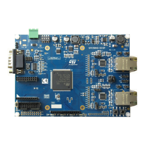
UM2255 SPC58NG-DISP SPC58NG-DISP Figure 1. SPC58NG-DISP The SPC58NG-DISP discovery board is based on the microcontroller SPC58NG84E7, a high performance ® e200z4d triple core 32-bit Power Architecture technology CPU, 6 MB Flash with HSM cryptography in an eTQFP176 package. The several interfaces including GPI/O's, peripherals such as DSPI, LINFlexD (LIN and UART), FlexRay, M_CAN ISO CAN-FD and two ethernet ports make the SPC570S-DISP an excellent starter kit for the customer to quickly evaluate the microcontroller as well as to develop and debug application. -
Page 3: I/O Interface And Connectors
UM2255 I/O interface and connectors I/O interface and connectors • 2 ethernet ports 100BASE-TX • 1 CAN FD port with DB9 connector • 1 CAN + 1 LIN/UART +1 SPI • 2 FlexRay channels • JTAG (header 2 x 7 pin) •... -
Page 4: Spc58Ng-Disp Block Diagram
UM2255 SPC58NG-DISP block diagram SPC58NG-DISP block diagram Figure 2. SPC58NG-DISP block diagram SPC58NG84E7 UM2255 - Rev 3 page 4/16... -
Page 5: Hardware Overview
UM2255 Hardware overview Hardware overview Figure 3. SPC58NG-DISP: HW overview Power supply section Figure 4 shows the PSU block diagram. The DC input source is 12 V and the three voltage regulators generate 5 V, 3.3 V and 1.2 V supply voltages. -
Page 6: Power Supply - Jumper Configuration
UM2255 Power supply section 3.1.1 Power supply - jumper configuration U2 provides 3.3 V output voltage used to supply the VDD_HV pins. The test point J5 can be used to monitor the VDD_HV supply voltage level. The VDD_LV pin can be supplied using an internal regulator and a ballast BJT or providing the supply by using an external source. -
Page 7: Microcontroller Section
UM2255 Microcontroller section Microcontroller section 3.2.1 Programmer/debugger JTAG port A standard 14 pin JTAG port is available for programming and debugging (Figure Figure 6. JTAG connector UM2255 - Rev 3 page 7/16... -
Page 8: User Leds And User Buttons
UM2255 User LEDs and user buttons User LEDs and user buttons In the board, the following functions are available: • 4 LEDs (Figure • 2 push buttons (Figure • 4 DIP switches (Figure Figure 7. User LEDs Figure 8. User push buttons Figure 9. -
Page 9: Ethernet Configuration
UM2255 Ethernet configuration Ethernet configuration Figure 10. Ethernet configuration UM2255 - Rev 3 page 9/16... -
Page 10: Ethernet Mii / Rmii Configuration
UM2255 Ethernet configuration 3.4.1 Ethernet MII / RMII configuration Table 2. Ethernet MII jumper configuration Default configuration - MII Jumper Jumper setting JP205 JP201 JP211 JP209 JP210 JP208 Table 3. Ethernet RMII jumper configuration Default configuration - RMII Jumper Jumper setting JP205 JP201 JP211... -
Page 11: Can-Fd
CAN-FD section with the transceiver and the DB9 connector. Figure 11. CAN-FD Communication daughter board socket The functionality of SPC58NG-DISP increases the plugging of some additional daughter boards in the connectors P301, P301B, P301C and P301D (see Figure 12). -
Page 12: Revision History
UM2255 Revision history Table 6. Document revision history Date Version Changes 31-Jul-2017 Initial release. Updated Introduction. 03-Sep-2018 Minor text changes. Updated title in cover page. Updated Section 3.1.1 Power supply - jumper configuration and moved from previous to 18-Feb-2021 current position. Minor text changes. -
Page 13: Table Of Contents
SPC58NG-DISP block diagram ........ -
Page 14: List Of Tables
UM2255 List of tables List of tables Table 1. Power supply - jumper configuration ............6 Table 2. -
Page 15: List Of Figures
SPC58NG-DISP block diagram........ - Page 16 ST’s terms and conditions of sale in place at the time of order acknowledgement. Purchasers are solely responsible for the choice, selection, and use of ST products and ST assumes no liability for application assistance or the design of Purchasers’...
Need help?
Do you have a question about the SPC58NG-DISP and is the answer not in the manual?
Questions and answers