Table of Contents
Advertisement
Quick Links
UM2827
User manual
SPC58XXADPT144S rev. B evaluation board
Introduction
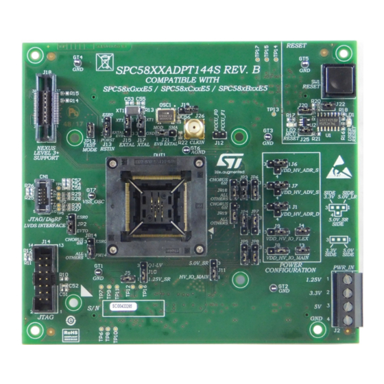
The SPC58XXADPT144S rev. B evaluation board supports STMicroelectronics SPC58xGxxE5, SPC58xCxxE5 and
SPC58xBxxE5 microcontrollers in eTQFP144 package with exposed pad down.
Figure 1.
SPC58XXADPT144S rev. B
Note: Picture not contractual
UM2827 - Rev 1 - February 2021
www.st.com
For further information contact your local STMicroelectronics sales office.
Advertisement
Table of Contents

Subscribe to Our Youtube Channel
Related Manuals for ST SPC58XXADPT144S


Summary of Contents for ST SPC58XXADPT144S
- Page 1 UM2827 User manual SPC58XXADPT144S rev. B evaluation board Introduction The SPC58XXADPT144S rev. B evaluation board supports STMicroelectronics SPC58xGxxE5, SPC58xCxxE5 and SPC58xBxxE5 microcontrollers in eTQFP144 package with exposed pad down. Figure 1. SPC58XXADPT144S rev. B Note: Picture not contractual UM2827 - Rev 1 - February 2021 www.st.com...
-
Page 2: Overview
UM2827 Overview Overview The SPC58XXADPT144S rev. B "mini module" is an evaluation board supporting STMicroelectronics SPC58xGxxE5, SPC58xCxxE5 and SPC58xBxxE5 microcontrollers in eTQFP144 package with exposed pad down. The "mini module" is designed to be connected onto the SPC58xxMB motherboard, offering a mechanism for easy customer evaluation of the supported devices, and to facilitate hardware and software development. -
Page 3: Package Contents
An SPC58XXADPT144S rev. B adapter package includes the following item: • SPC58XXADPT144S rev. B "mini module" Supported devices The SPC58XXADPT144S rev. B "mini module" supports the following STMicroelectronics family of microcontrollers in eTQFP144 package with exposed pad down: • SPC58xBxxE5 •... -
Page 4: License Agreement
Attention: This evaluation board only offers limited features for evaluating ST products. It has not been tested for use with other products and is not suitable for any safety or other commercial or consumer application. This evaluation board is otherwise provided “AS IS”... -
Page 5: Handling Precautions
UM2827 Handling precautions Handling precautions Please take care to handle the package contents in a manner such as to prevent electrostatic discharge. Before the EVB is used or power is applied, please fully read the following sections on how to correctly configure the board. -
Page 6: Hardware Description
UM2827 Hardware description Hardware description Hardware features The SPC58XXADPT144S rev. B "mini module" board has the following features: • Connector for external power supplies input (5.0 V, 3.3 V, 1.25 V) used in stand-alone mode • Reset button with driver and led indicator •... -
Page 7: Power And System Configuration
When the "mini module" is plugged onto the motherboard, power is supplied directly by the motherboard. In this setup, the external power supply input available on the "mini module" should NOT be used. When the SPC58XXADPT144S rev.B "mini module" is used as a stand-alone board, external power supplies must be used (5 V, 3.3 V, 1.25 V). -
Page 8: System Clock Configuration
Jumper Description Default Position 40 MHz crystal clock source enable Figure 4. SPC58XXADPT144S rev. B "mini module" - top 1-2 (XT1 pin2) for pin EXTAL 40 MHz crystal clock source enable Figure 4. SPC58XXADPT144S rev. B "mini module" - top... -
Page 9: Port Configuration
Ports related jumpers Jumper Description Default Position Close (10 KΩ pull- JP13 TESTMODE settings Figure 4. SPC58XXADPT144S rev. B "mini module" - top - A2 down) RSTIN configuration • 1-2: ESR0 Figure 4. SPC58XXADPT144S rev. B "mini module" - top - B2 (PORST) •... -
Page 10: Spc58Xg Configuration
Table 5. SPC58xG configuration related jumpers Jumper Description Default Position Device pin 134 port Figure 5. SPC58XXADPT144S rev. B "mini (closed with PCB trace for connect configuration module" - bottom - B3 pin 134 to PC[13] ) Device pin 133 port Figure 5. -
Page 11: Test Points
Table 6. Test points Test point Description Position GND test point Figure 4. SPC58XXADPT144S rev. B "mini module" - top - A4 GND test point Figure 4. SPC58XXADPT144S rev. B "mini module" - top - C4 GND test point Figure 4. SPC58XXADPT144S rev. B "mini module" - top... -
Page 12: Connectors
Connectors Connectors Description Position 38-pin Mictor connector for Nexus level 3+ Figure 4. SPC58XXADPT144S rev. B "mini module" - top - A1 14-pin header connector for JTAG interface Figure 4. SPC58XXADPT144S rev. B "mini module" - top - A3 10-pin header connector for JTAG/DigRF Figure 4. -
Page 13: Layout Overview
UM2827 Layout overview Layout overview Figure 4. SPC58XXADPT144S rev. B "mini module" - top UM2827 - Rev 1 page 13/25... -
Page 14: Figure 5. Spc58Xxadpt144S Rev. B "Mini Module" - Bottom
UM2827 Layout overview Figure 5. SPC58XXADPT144S rev. B "mini module" - bottom UM2827 - Rev 1 page 14/25... -
Page 15: Bom
UM2827 Table 8. Item QTY Reference Manufacturer code Value Part description C1, C4, C10, C28, Mult. cer. cap. 16V 0805 - automotive 2.2 uF C31, C46, C47, C50 series - not mounted C2, C5, C8, C11, C13, C15, C17, C19, 100 nF Mult. - Page 16 UM2827 Item QTY Reference Manufacturer code Value Part description Conn. SMD TYCO , vertical, female, 38P 5767054-1 MICTOR - GND pin lenght 2.74 mm STRIP2PM Malestrip 2 poles see mech part - OPEN J20, J22, J25 STRIP2PM Male strip 2 poles see mech part - CLOSE SAMTEC SAMTEC 0.5 mm pitch high speed SMD J23, J24...
-
Page 17: Schematics
Schematics Figure 6. Power and decoupling 5.0V_LR 3.3V_SR 5.0V_SR 1.25V_SR VDD_HV_ADR_D Used only for CHORUS 6M 1.25V_SR 3.3V_SR 5.0V_SR VDD_HV_ADR_D 5.0V_SR 1/10W DEFAULT 2.2uF 100nF 10nF 0805 1-2 CLOSED 0805 0603 0603 N.M. AGND AGND AGND MC-31072104 VDD_HV_ADR_S 5.0V_SR 1/10W DEFAULT 2.2uF 100nF... -
Page 18: Figure 7. Signals
Figure 7. Signals PE[0..15] CLKOUT PE[0..15] 1/10W 0603 TCK / PA[6] PE[0] TMS/Txp TMS / PA[7] PE[1] TDI/Txn TDI / PA[8] PE[2] TDO/Rxp TDO / PA[9] PE[3] / CLKOUT JCOMP/Rxn JCOMP / PA[5] PE[5] PE[6] PA[0..15] PE[7] PA[0..15] PE[8] PE[9] PE10 PE[10] PE11... -
Page 19: Figure 8. Jtag, Jtag/Lfast Lvds Interface, Reset And Crystal
Figure 8. JTAG, JTAG/LFast LVDS INTERFACE, reset and crystal Nexus level 3+ support Jtag interface VDD_HV_IO_MAIN J TAG, J TAG/Di g RF LVDS INTE RF ACE , Ne x u s Le ve l 3 + VDD_HV_IO_MAIN JTAG Connector NOT MOUNTED 0R DNP 1/10W 0603... -
Page 20: Figure 9. Motherboard Connectors
Figure 9. Motherboard connectors PortA PortB PortC PortD PortF PortG PortH PortI PortM PortE PA[0..15] PB[0..15] PC[0..15] PD[0..15] PE[0..15] PF[0..15] PG[0..15] PH[0..15] PI[0..15] PK[0..15] PM[0..15] PA[0..15] PB[0..15] PC[0..15] PD[0..15] PE[0..15] PF[0..15] PG[0..15] PH[0..15] PI[0..15] PK[0..15] PM[0..15] PK14 PM14 PA10 PB10 PC10 PD10 PE10... -
Page 21: Revision History
UM2827 Revision history Table 9. Document revision history Date Version Changes 17-Feb-2021 Initial release. UM2827 - Rev 1 page 21/25... -
Page 22: Table Of Contents
UM2827 Contents Contents Overview ................2 Package Contents. - Page 23 UM2827 List of tables List of tables Table 1. Supply related jumpers ..............7 Table 2.
- Page 24 Overview of SPC58XXADPT144S rev. B "mini module" - bottom ....... .
- Page 25 ST’s terms and conditions of sale in place at the time of order acknowledgement. Purchasers are solely responsible for the choice, selection, and use of ST products and ST assumes no liability for application assistance or the design of Purchasers’...
Need help?
Do you have a question about the SPC58XXADPT144S and is the answer not in the manual?
Questions and answers