
Related Manuals for molex 57030-3000


Summary of Contents for molex 57030-3000
- Page 1 INSTRUCTION SHEET NO. IS-0006E INSTRUCTION FOR OPERATION AND ADJUSTMENT OF ISSUED DATE 1980, JAN 1. REVISED DATE 2015,May 25 MODULAR CRIMP DIE JM××××A MODEL NO. 57×××-3000 MODEL NO.57030-3000...
- Page 2 --*For the Safety Operation *-- Do not start your Modular Crimp Die until you have read and acquainted yourself with these instruction! Safety cover should be mounted in proper manner for crimping operation.
-
Page 3: Table Of Contents
CONTENTS 1.DESCRIPTION -------------------------------------------------------------------------------------- 2. 2. MECHANISM AND ADJUSTMENT -------------------------------------------------------------- 2. 2-1. CONDUCTOR CRIMP HEIGHT ADJUSTMENT MECHANISM -------------------------- 2. 2-2. INSULATION CRIMP HEIGHT ADJUSTMENT MECHANISM -------------------------- 2. 2-3. FEED LENGTH ADJUSTMENT MECHANISM -------------------------------------- 3. 2-4. FEED PAWL FINGER LOCATION ADJUSTMENT MECHANISM -------------- 5. -
Page 4: Description
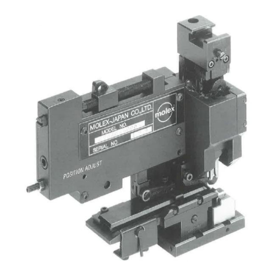
Description. Molex Japan Modular Crimp Die is designed and developed to save time, Money and man-hour for crimping operation as well as to make precise termination. It is very easy to mount on/or remove from the Crimping Machine M15A, Therefore versatile Crimping are possible to possess several Modular Dies. -
Page 5: Insulation Crimp Height Adjustment Mechanism
3 — Push Adjust Rod ⑫ by a screw driver until Pin (61) Provided on Adjust Rod is come off from Identification Plate ⑪ 4— Turn Adjust Rod to the mark selected by paragraph 2 and release it so Adjust Rod is pushed back by Spring (58) to seat pin (61) in the selected mark position, Then selected crimp height is to obtained. -
Page 6: Feed Length Adjustment Mechanism
2— Turn Adjust Rod (13) to align selected number to Indication mark (See illustration 2) and release it. 3— Adjust Rod (13) is pulled back by Compression Spring (57) , and fallen into cavity of Ram. Then selected insulation crimp height is to be obtained, 4—... -
Page 7: Feed Pawl Finger Location Adjustment Mechanism
3—Performing this adjustment, feed finger location may be shifted, therefore adjustment of feed finger location should be performed afterwards. After completion of adjustment, tighten Lock Bolt (80). 4— Confirm feed length by 2—3 times manual operation. Note: For the manner by manual operation, please refer to Manual Operation Procedure described in Crimping Machine instructions. - Page 8 Procedure: (See illustration?) 1—Loosen Lock Bolt (88) provided on the Block (26). 2—Turn Adjust Rod (28) provided on the Block (26). Then terminal strip guide assembly is shifted back and forth. TURN TO LENGTH OF LENGTH OF TERMINAL BELL MOUTH CUT-OFF SHIFTED TO CLOCKWISE...
-
Page 9: To Mount Modular Crimp Die To Crimping Machine Ml5A
3. To mount Modular Crimp Die to Crimping Machine M15A Modular dies are designed to mount on/or remove from crimping machine M15A very easily. Procedure; 1—A hanging hook is provided on the ram of crimping machine, Hang Holder Block of Modular crimp die on this hook. 2—Pull down Modular Die toward Bolster. -
Page 10: Replacement Or Mounting Procedure For Perishable Parts
*Conductor crimp height adjustment This adjustment may be applied in case of modular die is replaced, of specified crimp height is not obtained on normal crimping operation. 1— Select proper conductor crimp height mark [A, B, C or D] for wire size to be used. - Page 11 4—2. Replacement of conductor punch of insulation punch. l—Pu1l out Ram assembly. — Take off tip of feed finger from the hole of the carrier, and pull fully to anvil direction. Then Ram assembly is able to remove from body very easily. 2—Remove mounting volt (77) to remove punches.
-
Page 12: Matters To Be Attended To
4-3. Replacement of Floating Shear and Holder. 1—A pair of mounting bolt (74) are placed under the base plate. Remove these bolts, then Holder (6) is to remove together with Floating Shear (5) and Spring. (In order to replace Floating Shear only, loosen the bolt provided on Holder). -
Page 13: Daily Maintenance
3—It' it is need to use special with, Please contact our Field Service department on details. 4—Please keep and maintain Modular Dies removed from the crimping machine with inserting applicable terminal between punch and anvil, for preventing from interference between punch and anvil. 5—Please Clean out any grit, dirt or foreign matter from the parts and area where parts may be mounted, in case of replacement of perishable parts. -
Page 14: Crimping Procedure For The Same Series Terminal
To replace 8. Crimping procedure for the same series terminal. Molex Japan Modular Crimp Die is applicable to crimp the same series terminal with replacing applicable parts. For the applicable parts, please refer to the Parts List on each modular die respectively please refer to the following paragraphs for replacement procedure. - Page 15 ? If you have any further questions on Molex Japan Modular Crimp Die, please contact our Field Service. ISSUED BY : ENGINEERING DEPT. MOLEX-JAPAN 1995. 5.
- Page 16 Molex Japan LLC 1-5-4 Fukami-Higashi Yamato, Kanagawa Japan 242-8585 Direct +81.46.265.2322 Fax +81.46.265.2379...
Need help?
Do you have a question about the 57030-3000 and is the answer not in the manual?
Questions and answers