Advertisement
Quick Links
Advertisement

Related Manuals for Nucraft ALEV CLASSIC


Summary of Contents for Nucraft ALEV CLASSIC
- Page 1 Alev Installation Instructions...
-
Page 2: Before Beginning Installation
Before Beginning Installation • Read through the entire instruction thoroughly. • A minimum of 2-3 persons is required for this assembly. Larger tables above 132” will need more people for multi section frame assembly. • These instructions reflect typical assemblies. They may not match your specific configuration. - Page 3 Provided Hardware HW0747: Screw #10X.625, PH, PHIL HW1093: Bolt .25 -20X.75, HXF, ZN, SERR HW1094: Nut .25-20, HXF, ZN, SERR HW2248: Bolt .312-18X.625, SKT C/S HW4640: Screw - #12X1”, PH, PH, TY-17, ZP HW8013: Screw - .25 X 20X .315 THUMB...
- Page 4 Alev Classic Segmented...
- Page 5 Step 1: Metal Frame and Legs • **One person to lift the frame up in the air (one end at a time), while a second person attaches the legs. Multi piece tables will be easier to attach the legs to the end frame sections. Then attach end frames to middle frame sections. •...
- Page 6 Step 2: Wood Legs • Wood legs slide over the steel legs, and rest in place. • These will be fastened later in the process. • ** Each end of the frame to be lifted in the air and slowly lowered down onto the wood leg. 2-3 people will be needed for this due to the weight of the frame.
- Page 7 Step 3: Structural Center Column • (optional) Tables under 132” in length have a wire manager center column. This gets attached AFTER the shroud in step 4. • (non optional) Tables over 132” in length have a structural center column. Use bracket plates at top of column to fasten component to frame beam.
- Page 8 Step 4: Shroud Tables with power only: • Metal shroud fits on the underside of the frame by screwing in 4-8 thumb screws (HW8013) to the frame beam...
- Page 9 Step 5: Non Structural Center Column • (optional) Tables under 132” in length have an optional wire management center column. • The column can be placed anywhere along the central beam structure. Suggested location is centered. • Attach to frame with HW1093 and HW1094.
- Page 10 Step 6: Level Frame At this point use the glides on the bottom of the legs and the structural center column to level the frame.
- Page 11 Step 7A: Top – Segmented • Rest each section of the top onto the frame in the general location they will be secured. – See labels on the sections for proper ordering. • Starting with one end section; place plastic spline into the groove found on the edge of the top. Push the middle sections into one of the end sections to align the parts.
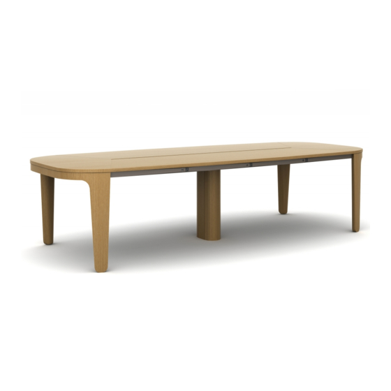
- Page 12 Step 7B: Top - Classic • Single piece top - place the top onto the frame. • Multi piece top - rest each section of the top onto the frame, in the general position they will end up being secured. –...
- Page 13 Step 8: Secure Top to Frame • Into the underside of the top, screw the leg plates to the work surface first, keeping the wood leg top edge as flush to the work surface edge as possible. • Then follow with screwing the frame half moon plates to the work surface. Use fasteners HW4640.
- Page 14 Step 9: Aprons • Aprons with perimeter power - Assemble plug units into the brackets. This is easier to do before screwing the apron in place under the table. • Hold the apron up to the underside of the top. Slowly bring the apron towards yourself so the ends of the apron tuck into the cutout in the legs.
- Page 15 Step 10: Modular Power System/ Wire Management • Connect the modular power system per the separate installation instructions. • Run the cords from the back of the power units, in the aprons, through the mouse hole in the frame beam. •...
- Page 16 Step 11A: (optional) Surface Power – Power Matrix • Use the separate installation instructions for the power matrix unit. • NOTE: Alev specifically uses spacer plates between the metal pan and wood top to help flush the top of the power matrix door to the top of the table.
- Page 17 Step 11B: (optional) Surface Power – Power Cap Set power cap in the cutout in the top. Use provided bracket on the underside of top to hold power cap in place.
Need help?
Do you have a question about the ALEV CLASSIC and is the answer not in the manual?
Questions and answers