Table of Contents
Advertisement
Quick Links
Instructions
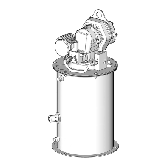
Dyna-Star
Pump System
Provides lubricant flow and pressure to operate a single line parallel automatic lubrication
system. For automatic lubrication systems only.
Not approved for use in European explosive atmosphere locations.
Models
77X202 - MODULE, EDS, HP, AFSO, LL, 60 lb
77X203 - MODULE, EDS, HP, AFSO, LL, 90 lb
77X402 - MODULE, EDS, HP, SP, AFSO, LL, 60 lb
77X403 - MODULE, EDS, HP, SP, AFSO, LL, 90 lb
24VDC, Injector module with pump, tube-in-tube, vent valve,
auto-fill shutoff, low level, 60 lb. or 90 lb. reservoir.
3500 psi (24.1 MPa, 241 bar) Maximum Working Pressure
5000 psi (34 MPa, 344.7 bar) Maximum Refilling Inlet Pres-
sure
Important Safety Instructions
Read all warnings and instructions in this
manual, the Dyna-Star HP and HF Pump
instruction manual and all related component
manuals (listed below). Save all instructions.
Related Manuals
Manual
332514
Dyna-Star HP and HF Pump
Dyna-Star HP and HF Auto-Fill Shut
332518
Off Kit
332519
Dyna-Star HP Vent Valve Kit
333393
Fill Valve
334998
Power Cable Kit
334999
Cable Harness Kit
3A2960
GLC2200 Lubrication Controller
®
HP
Description
3A3956D
EN
Advertisement
Table of Contents

Subscribe to Our Youtube Channel
Related Manuals for Graco Dyna-Star HP 77X202


Summary of Contents for Graco Dyna-Star HP 77X202
- Page 1 Instructions ® Dyna-Star Pump System 3A3956D Provides lubricant flow and pressure to operate a single line parallel automatic lubrication system. For automatic lubrication systems only. Not approved for use in European explosive atmosphere locations. Models 77X202 - MODULE, EDS, HP, AFSO, LL, 60 lb 77X203 - MODULE, EDS, HP, AFSO, LL, 90 lb 77X402 - MODULE, EDS, HP, SP, AFSO, LL, 60 lb 77X403 - MODULE, EDS, HP, SP, AFSO, LL, 90 lb...
-
Page 2: Table Of Contents
Refilling Systems without a Fill Valve ..16 Refilling Systems with a Fill Valve (Z) ..18 Troubleshooting ............. 20 Parts List: ..............22 Accessories ..........22 Technical Specifications ........23 Dimensions ............. 24 Notes ................ 25 Graco Standard Warranty ........26 Graco Information ..........26 3A3956D... -
Page 3: Warnings
Warnings Warnings The following warnings are for the setup, use, grounding, maintenance, and repair of this equipment. The exclama- tion point symbol alerts you to a general warning and the hazard symbols refer to procedure-specific risks. When these symbols appear in the body of this manual or on warning labels, refer back to these Warnings. Product-specific hazard symbols and warnings not covered in this section may appear throughout the body of this manual where applicable. - Page 4 Warnings EQUIPMENT MISUSE HAZARD Misuse can cause death or serious injury. • Do not operate the unit when fatigued or under the influence of drugs or alcohol. • Do not exceed the maximum working pressure or temperature rating of the lowest rated system com- ponent.
-
Page 5: Typical Installation: Injector System
Systems with Pressure Relief Valve in the Refilling Line The installation shown is only a guide for selecting and installing system components. Contact your Graco distributor for assistance in planning a system to suit your needs. NOTE: The remote filling station pump stalls (dead-heads) when the reservoir is full. -
Page 6: Typical Installation: Series Progressive System
Typical Installation: Series Progressive System Typical Installation: Series Progressive System The installation shown below is only a guide for selecting and installing system components. Contact your Graco dis- tributor for assistance in planning a system to suit your needs. Back... -
Page 7: Systems With Fill Valve In The Refilling Line
Systems with Fill Valve in the Refilling Line The installation shown is only a guide for selecting and installing system components. Contact your Graco distributor for assistance in planning a system to suit your needs. NOTE: The remote filling station pump stalls (dead-heads) when the reservoir is full. -
Page 8: Installation
This equipment stays pressurized until pressure is NOTE: Cable wiring harness kits are available from manually relieved. To help prevent serious injury from Graco. See Parts page 22 for a complete list of available pressurized fluid, such as skin injection, splashing kits. -
Page 9: Wire Connection Table
Installation Pump Connection with Graco Wiring Harness 77X546 See F Wire Connection Table Wire Color Connection Orange Signal + Black Power - Power + Blue Signal - 3A3956D... -
Page 10: 24 Vdc With Signal Input
Installation User Supplied Wiring Harness 24 VDC With Signal Input . 7: Pump control switch shown in signal mode *A Vent Valve is only used in an injector-based system. 24 VDC With External Relay . 8: Pump controls switch shown in power mode *A Vent Valve is only used in an injector-based system. -
Page 11: Motor Control Board
Installation Motor Control Board • SIG - Turns pump on when voltage is applied to: + (Positive) Power Input - SIG IN - - SIG IN + - (Negative) Power Input Blue Motor Wire Connection Turn On Signal - Yellow Motor Wire Connection Turn On Signal + Green Motor Wire Connection Red (Fault) LED - Blinks type of fault (See Fault Table) -
Page 12: Fault Table: Red Led (E)
Installation Fault Table: Red LED (E) Fault Blinks Over Current Locked Rotor Low or High Voltage High Motor temp Missing Temp Sensor High Board Temp Bad Hall Cable Pump Control Operation NOTICE To avoid equipment damage, remove power before switching modes from signal to power or power to sig- nal. -
Page 13: Reservoir Mounting
Installation Reservoir Mounting 3. The lubrication controller (F) terminates the signal to the pump (B) and power to the vent valve (L). 4. The vent valve (L) opens. 5. Pressure in the supply line (D) is relieved back into the reservoir, resetting all injectors (E). LIFTING HAZARD This equipment is heavy. -
Page 14: Refilling Line Requirements
There is still lubricant in the tank and A Pressure Relief Kit: 247902 is available from Graco. immediate shutdown is not required. Contact your distributor or Graco Customer Service for additional information about this kit. - Page 15 Installation Low Level Sensor Wiring with GLC2200 Lube Controller Pin Connector . 12 . 13 6LC-4400 . 14 3A3956D...
-
Page 16: Auto-Fill Shut Off
Installation Auto-Fill Shut Off Refilling the Reservoir The Auto-Fill Shut Off (S) is used for refilling the grease Refilling Systems without a Fill Valve tank/reservoir in an automatic lubrication system. When the grease level in the tank is full, the Auto-Fill Shut Off 1. - Page 17 Installation b. Close ball valve (bv) when all pressure has been relieved. NOTE: The pin may not drop and the Auto-Fill Shut Off may not reset because the tank is full. However, when the pump begins using the grease, the pin resets. The pin must reset 4.
-
Page 18: Refilling Systems With A Fill Valve (Z)
Installation Refilling Systems with a Fill Valve (Z) The reference letters used in the following instructions down refer to the Typical Installation diagrams provided, F 3, page 7. 1. Prior to starting the fill, pull out and hold black Pres- sure Relief Knob (Z1) long enough to relieve line pressure between Fill Valve (Z) and Auto-Fill Shut Off Valve (S). - Page 19 Disconnect the refilling line (AA) at the fill cou- pler (Z3). d. Replace the yellow dust cover (Z2). Service Use only Genuine Graco Repair Parts. See separate system component manuals for service instructions. For pump service see manual 332514. For vent valve service see manual 332519.
-
Page 20: Troubleshooting
Troubleshooting Troubleshooting Problem Cause Solution Pump (B) malfunction. Refer to the pump manual 332514. Pump (B) is not running; i.e., not cycling, there is no lubricant output, pump runs slow, the control board’s red LED fault is illuminated, etc. Blockage in the line. Check for blockage in the line. - Page 21 Troubleshooting Problem Cause Solution Low level alarm did not come on but Check sensor LED. If green, tank has Low level sensor malfunction pump cavitates (runs out of grease). grease but pump is not able to pump grease. See Troubleshooting instruc- tions in pump manual 332514.
-
Page 22: Parts List
Parts List: Parts List: Accessories Ref. Part No. Description Part No. Description 77X011 Pump and vent valve, 60#, includes 24N468 GLC2200 Lube Controller (Series F or 1a and 1b (77X202) later only) 77X012 Pump and vent valve, 90#, includes Cable Harness Kits 1a and 1b (77X203) 129072 CABLE, low level... -
Page 23: Technical Specifications
Technical Specifications Technical Specifications Dyna-Star Pump Metric Maximum working pressure 3500 psi 24.1 MPa, 241 bar Grease capacity 60 lb 27 kg 90 lb 41 kg Lubricant outlet port size 3/8 npt (f) Fill port size (Auto-Fill Shut Off) 3/8 npt (F . -
Page 24: Dimensions
Dimensions Dimensions 60 lb Models 90 lb Models US (inch) Metric (cm) US (inch) Metric (cm) 77.47 96.52 30.5 38.0 14.5 36.83 14.5 36.83 19.4 49.28 27.0 68.6 Ø Ø six, 7/16 inch hole six, 7/16 inch hole 13 7/8 inch bolt circle 13 7/8 inch bolt circle 14.5 36.83... -
Page 25: Notes
Notes Notes 3A3956D... -
Page 26: Graco Standard Warranty
With the exception of any special, extended, or limited warranty published by Graco, Graco will, for a period of twelve months from the date of sale, repair or replace any part of the equipment determined by Graco to be defective.
Need help?
Do you have a question about the Dyna-Star HP 77X202 and is the answer not in the manual?
Questions and answers