Table of Contents
Advertisement
Quick Links
Omega 4K/UHD Scaler for HDBaseT and HDMI
AT-OME-RX31
The Atlona AT-OME-RX31 is an HDBaseT receiver, three-input switcher, and 4K/UHD scaler
with a local HDMI input. Part of the Omega™ Series of integration products for modern AV
communications and collaboration, the OME-RX31 features two HDBaseT inputs for receiving
video up to 4K/60 4:2:0, plus embedded audio, control, Ethernet, and USB over distances up
to 330 feet (100 meters). The HDMI input supports video up to UHD/60 4:4:4. The OME-RX31 is
HDCP 2.2 compliant and features 4K/60 upscaling and downscaling with frame rate conversion.
Additionally, it provides integrated control for displays and room functions such as motorized
screens, and can be externally triggered with the addition of an occupancy sensor. The OME-
RX31 is ideal for 4K presentation applications with Omega, HDVS-200, or UHD-EX Series
transmitters, as well as Atlona AV presentation switchers with HDBaseT outputs, local HDMI
sources, and the Gain™ Series amplifiers.
Package Contents
1 x AT-OME-RX31
2 x Mounting brackets
4 x Mounting screws
2 x 5-pin captive screw connector
1 x 4-pin captive screw connector
1 x 3-pin captive screw connector
1 x 24 V DC power supply
1 x Installation Guide
IMPORTANT: Visit http://www.atlona.com/product/AT-OME-RX31 for the latest firmware
updates and documentation.
1
Installation Guide
AT-OME-RX31
Advertisement
Table of Contents

Subscribe to Our Youtube Channel
Related Manuals for Panduit Atlona AT-OME-RX31


Summary of Contents for Panduit Atlona AT-OME-RX31
- Page 1 Omega 4K/UHD Scaler for HDBaseT and HDMI AT-OME-RX31 The Atlona AT-OME-RX31 is an HDBaseT receiver, three-input switcher, and 4K/UHD scaler with a local HDMI input. Part of the Omega™ Series of integration products for modern AV communications and collaboration, the OME-RX31 features two HDBaseT inputs for receiving video up to 4K/60 4:2:0, plus embedded audio, control, Ethernet, and USB over distances up to 330 feet (100 meters).
-
Page 2: Panel Descriptions
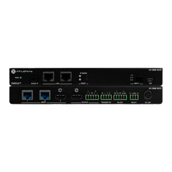
Installation Guide AT-OME-RX31 Panel Descriptions Front AT-OME-RX31 IP MODE OMEGA SHOW IP RESET INPUT AT-OME-RX31 TX RX COM C2 This LED indicator glows solid green when the unit is powered. INPUT OUTPUT TRIGGER I/O RS-232 RELAY DC 24V SHOW IP Press and release this button to display the IP address of the AT-OME-RX31 on the connected display. - Page 3 Installation Guide AT-OME-RX31 AT-OME-RX31 Panel Descriptions IP MODE OMEGA SHOW IP RESET INPUT Rear AT-OME-RX31 TX RX COM C2 INPUT OUTPUT TRIGGER I/O RS-232 RELAY DC 24V INPUT (HDBaseT) Connect up to two category cables (CAT-5e or better) from each of these ports to a compatible HDBaseT transmitter.
-
Page 4: Audio Output Connector
Installation Guide AT-OME-RX31 Audio Output Connector The AT-OME-RX31 provides two-channel LPCM audio de-embedding of the source device, using a dedicated audio output port. Unbalanced Side View Side View Balanced Rear View Rear View Use wire strippers to remove a portion of the cable jacket. Remove at least 3/16”... - Page 5 Installation Guide AT-OME-RX31 TRIGGER I/O Connector The TRIGGER I/O port allows voltage-controlled devices, such as an occupancy sensor, to be connected to the AT-OME-RX31. Use the included 4-pin captive screw connector to connect the device. The voltage range is 3 V to 30 V DC. Powered Sensor Powered sensor 30 V (max.)
- Page 6 Installation Guide AT-OME-RX31 RS-232 Connector The AT-OME-RX31 provides an RS-232 port for RS-232 control. RS-232 1 is used for controlling the connected display. RS-232 2 is used for controlling the AT-OME-RX31. Note that the ground pin is shared between port 1 and port 2. NOTE: Typical DB9 connectors use pin 2 for TX, pin 3 for RX, and pin 5 for ground.
-
Page 7: Relay Connector
Installation Guide AT-OME-RX31 RELAY Connector The RELAY port allows the control of screens, curtains, and other devices. Use a 48 V DC relay with no more than 1 A current draw. When the AT-OME-RX31 is powered-on or rebooted, C1 and C2 are set to the Normally Open (NO) state. -
Page 8: Installation
Installation Guide AT-OME-RX31 Installation Connect an Ethernet cable from one of the LAN ports to the Local Area Network. Connect another Ethernet cable from one of the LAN ports to a display device, allowing IP control. Connect up to category cables (CAT-5e or better) from compatible HDBaseT transmitters to the INPUT 1 and INPUT 2 ports. -
Page 9: Mounting Instructions
Installation Guide AT-OME-RX31 Mounting Instructions The AT-OME-RX31 includes two mounting brackets, which can be used to attach the unit to any flat surface. Use the two enclosure screws, on the sides of the unit to attach the mounting brackets. Using a small Phillips screwdriver, remove the two screws from the left side of the enclosure. - Page 10 Installation Guide AT-OME-RX31 IP Configuration The AT-OME-RX31 is shipped with DHCP enabled. Once connected to a network, the DHCP server (if available), will automatically assign an IP address to the unit. If the AT-OME-RX31 is unable to detect a DHCP server within 15 seconds, then the unit will use a self-assigned IP address within the range of 169.254.xxx.xxx.
-
Page 11: Resetting To Factory Defaults
Installation Guide AT-OME-RX31 Resetting to Factory-Defaults To reset the AT-OME-RX31 to factory-default settings, press and hold the RESET button for approximately 5 seconds. Release the button when the RESET LED indicator begins to flash. The LED indicator will flash three times to indicate that the reset procedure has completed. IP Mode button AT-OME-RX31 IP MODE... -
Page 12: Front Panel Led Indicators
Installation Guide AT-OME-RX31 Front Panel LED Indicators The LED indicators on both the front and rear of the unit provide basic information on the current status of the unit. Description Solid green Unit is receiving power using the optional 24 V DC power supply.
Need help?
Do you have a question about the Atlona AT-OME-RX31 and is the answer not in the manual?
Questions and answers