MAHA MLT 3000 Original Operating Instructions
Headlight tester
Hide thumbs
Also See for MLT 3000:
- Original operating instructions (45 pages) ,
- Original operating instructions (33 pages)
Table of Contents
Advertisement
Advertisement
Table of Contents
Troubleshooting

Related Manuals for MAHA MLT 3000


Summary of Contents for MAHA MLT 3000
- Page 1 MLT 3000 Headlight Tester Original Operating Instructions BA380701-en...
- Page 2 BA380701-en 2018-11-20 © MAHA Maschinenbau Haldenwang GmbH & Co. KG The reproduction, distribution and utilization of this document as well as the communication of its con- tents to others without explicit authorization is prohibited. Offenders will be held liable for the payment of damages.
-
Page 3: Table Of Contents
Requirements for the Place of Installation ................7 Technical Data ........................7 Design............................. 8 Electronic Levelling ........................ 9 2.4.1 Compensation Coordinate Axes of MLT 3000 ............... 9 2.4.2 Angle Symbols ........................10 Definition of Technical Terms ....................11 2.5.1 Pitch Angle ........................... 11 2.5.2... - Page 4 3.4.1 Test Phase Indication via Light Buttons ................22 3.4.2 Measuring ..........................22 3.4.3 Light Selection Buttons Disabled ..................23 3.4.4 Adjusting: Setting the Headlights in Real Time..............24 3.4.5 Saving the Measurement Values to PDF ................25 Settings ..........................27 3.5.1 Variables ..........................
-
Page 5: Safety
Safety Introduction Thoroughly read this manual before operating the equipment and comply with the instructions. Always display the manual in a conspicuous location. Personal injury and property damage incurred due to non-compliance with these safety instructions are not covered by the product liability regulations. Symbols and Signal Words 1.2.1 Personal Injury... -
Page 6: Intended Use
Intended Use This device only serves to check and adjust the alignment of vehicle headlights. This device cannot be modified without the express, written consent of the manufacturer. Any infringement renders the conformity declaration invalid. Requirements on Operating and Service Personnel WARNING All persons employed in the operation, maintenance, installation, removal and disposal of the device must... -
Page 7: Description
Description Requirements for the Place of Installation Please observe your national guidelines and specifications. Technical Data Measuring range above hotspot 0…800 mm / 10 m (0…8 %) above pitch angle 0…300 mm / 10 m (0…3 %) below 0…700 mm / 10 m (0…7 %) left 0…1000 mm / 10 m (0…10 %) right... -
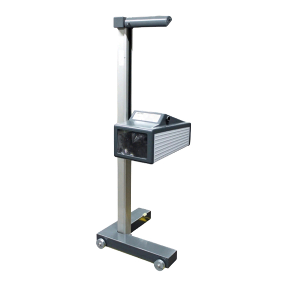
Page 8: Design
Design Mirror, with optional Charging socket laser alignment unit Column Casing, with adjusting handle Display Carriage, with spirit level USB port Battery compartment BA380701-en... -
Page 9: Electronic Levelling
See section “Operation > Settings > Calibrating the Camera according to Directive”. NOTICE This function must be enabled exclusively by authorised service technicians and is ap- plicable for the respective test surface only. 2.4.1 Compensation Coordinate Axes of MLT 3000 BA380701-en... -
Page 10: Angle Symbols
2.4.2 Angle Symbols Once the adjustment of the inclination sensor has been completed, an angle symbol appears in the info bar to indicate the adjusted/active inclination axes. Overview of symbols: Both axes adjusted/active, Z-axis active, headlight tester headlight tester ready for op- ready for operation eration Both axes active, inclination of... -
Page 11: Definition Of Technical Terms
Definition of Technical Terms 2.5.1 Pitch Angle Angle of inclination of light-dark limit against the test surface. The inclination of headlight lighting bundle against the test surface is expressed as a percentage, using 10 m as a reference parameter: H X 100 1000 2.5.2... -
Page 12: High Beam
Light-dark limit Boundary for light distribution between ‘top dark’ and ‘bottom light’ for low- beam lights. Inflection point Synonymous with the light-dark limit for asymmetric low-beam lighting. The deviation of the inflection point is expressed in %. 10 meters is used as the ref- erence dimension. -
Page 13: Operation
Operation Switching On / Off The headlight tester is operated via touchscreen buttons. The resistive touchscreen reacts to pressure and can also be operated while wearing work gloves. The On/Off button is on the right-hand side underneath the touchscreen. Press to confirm Switch Off. -
Page 14: Aligning
Aligning When using guide rails, position the device centrally in front of the vehicle. Without guide rails, the device must be adjusted in front of each headlight. Please ob- serve your national guidelines and specifications. The device is correctly aligned when two symmetrical reference points on the front of the vehicle are located on the black line of the alignment mirror. -
Page 15: Led Adjustment Aid (Option)
3.2.2 LED Adjustment Aid (Option) This optional unit is integrated into the window housing (A) above the Fresnel lens. The colour LEDs (B) pointing toward the vehicle indicate the direction of adjustment. Green LED = Optimum setting (corresponds to green rating in the display centre) Yellow LED = Minor deviation within tolerance range (corresponds to yellow direction arrows on the display) -
Page 16: Light Selection Buttons
Light Selection Buttons 3.3.1 Headlight Test according to § 29 StVZO (Germany) Headlight test according to § 29 StVZO (Germany). Use the OEM button for manufacturer-specific test instructions. BA380701-en... -
Page 17: Showing The Button Labels
3.3.2 Showing the Button Labels When the Info button is activated, the button labels are shown instead of the symbols. 3.3.3 Adjusting the Pitch Angle The pitch angle can be increased or reduced using the Arrow buttons. BA380701-en... -
Page 18: Choosing The Vehicle Class
3.3.4 Choosing the Vehicle Class The Truck/Car button activates the appropriate settings for the respective vehicle class. 3.3.5 Browsing back through the Test Screens Use the Back Arrow button to browse back through the test screens one by one. BA380701-en... -
Page 19: Choosing Between Left-Hand Or Right Hand Traffic
3.3.6 Choosing between Left-Hand or Right Hand Traffic Left-hand/Right-hand traffic can be changed under “User Settings”. Right-hand traffic is preset by default. 3.3.7 Manufacturer-Specific Test Instructions (OEM) OEM area! Perform the test according to manufacturer’s instructions. BA380701-en... - Page 20 Button “ALL“ makes several test levels available. Example: testing Volkswagen matrix headlights OEM area! Perform the test according to manufacturer’s instructions. BA380701-en...
-
Page 21: Navigating Through The Test Levels
3.3.8 Navigating through the Test Levels Use the Play button to open the activated test levels one by one. BA380701-en... -
Page 22: Testing The Headlights
Testing the Headlights 3.4.1 Test Phase Indication via Light Buttons Green dot = Headlight tested, measurement OK Red dot = Headlight tested, not OK Grey dot = Headlight without evaluation Adjusting direction: Yellow arrow = Minor deviation within tolerance range Red arrow = Outside tolerance 3.4.2 Measuring... -
Page 23: Light Selection Buttons Disabled
PA = Pitch Angle; IP = Inflection Point; I = Intensity Yaw and Rolling angles can be additionally activated under “User Settings”. Use the Camera button (bottom centre) to change from the Measuring menu to the Adjusting menu. 3.4.3 Light Selection Buttons Disabled During measurement the light selection buttons are disabled. -
Page 24: Adjusting: Setting The Headlights In Real Time
3.4.4 Adjusting: Setting the Headlights in Real Time Green light button = Current measurement Use the “New vehicle” button to change back to the Main menu. BA380701-en... -
Page 25: Saving The Measurement Values To Pdf
3.4.5 Saving the Measurement Values to PDF Using the USB stick button, all available test values can be saved as PDF to a USB stick. The button appears only in the Measuring and Adjusting menus and if a USB stick has been detected by the headlight tester. - Page 26 Overview of test results as PDF file (example) BA380701-en...
-
Page 27: Settings
Settings 3.5.1 Variables Limit values as well as user and customer variables can be set directly at the headlight tester. BA380701-en... - Page 28 Limit values, user and customer variables can be adjusted directly on the equipment. BA380701-en...
-
Page 29: User Settings
3.5.2 User Settings Quick access to all important settings. BA380701-en... -
Page 30: Language
3.5.3 Language Use the flag button to open the language selection. Choose the desired language. BA380701-en... -
Page 31: Calibrating The Camera According To Directive
3.5.4 Calibrating the Camera according to Directive Compensation values can be checked using button “Calibrate camera according to di- rective”. No password required. Choose between Cross hair / Spot laser. BA380701-en... - Page 32 BA380701-en...
-
Page 33: Country Specifications
3.5.5 Country Specifications Statutory requirements, limit values and country-specific settings. Switching back from some of the country-specific test procedures requires a password. BA380701-en... -
Page 34: Settings With Password
The disabled (greyed out) menu items can be accessed only by entering a service technician password. Adjustment of the headlight tester is permitted exclusively with the following calibration equipment approved by MAHA and must be performed by an authorised service technician. VP 990175... -
Page 35: List Of Variables (Extract)
3.5.7 List of Variables (Extract) User variables Default Percentage 0 / Degrees 1 Lux 0 / Candela 1 Target value Pitch angle Car Target value Pitch angle HGV Switch-off time of display in minutes 1200 10.1 RHT/LHT button enabled 1 / disabled 0 11.0 OEM in main menu enabled 12.0.1... -
Page 36: Interfaces And Software Updates
Interfaces and Software Updates Software updates are normally performed using a USB stick (FAT32). Procedure: 1 Download the current software version from the MAHA homepage. www.maha.de/downloads.htm 2 Open the ZIP file by double-clicking. 3 Select the MAHA folder with preset folder structure and copy it to a USB stick. - Page 37 BA380701-en...
-
Page 38: Eurosystem V7.50
Troubleshooting > Charging the Battery”) Wireless connection via Bluetooth, order number: VZ 990312 These interfaces can be used for establishing a connection to MAHA’s EUROSYSTEM software, which is included with the cable or Bluetooth module. Alternatively, the headlight tester can also be integrated into a EUROSYSTEM test lane. - Page 39 Test devices are connected automatically. After the measurement has been started, all measured values are transferred to EUROSYSTEM. The connection to the MLT 3000 is re- tained until EUROSYSTEM is quit. Select menu item <Display measurement values>. Select menu item <Light tester>.
- Page 40 The selected measurement data is dis- played in detail. Graphic representation of headlight ad- justment in EUROSYSTEM: Use the camera button on the MLT 3000 display to switch over to headlight ad- justment. EUROSYSTEM shows the coordi- nates, the measured values and the head- light image in real time.
-
Page 41: Energy Management And Troubleshooting
Energy Management and Troubleshooting Charging the Battery The plug of the charger is inserted into the round (Neutrik) connector on the underside of the housing (see Fig.). The charging process normally takes 11 hours. Full battery capacity is achieved when the battery voltage has exceeded 14.00 V during charging. -
Page 42: Battery Status
Battery Status 4.2.1 Battery Life The battery has a rated capacity of 9500mAh and can provide up to 20 hours of continuous workshop operation at an optimum environmental temperature of 20°C. 4.2.2 Energy Saving Function After 10 minutes of no activity, the display switches off. By tapping the touchscreen, the device is immediately ready for operation. -
Page 43: Data Recording For Error Analysis
4.2.5 Data Recording for Error Analysis The data records of the battery status allow for an optimum analysis in problem cases. A USB stick is needed for data recording. Records with a duration of more than 2 h can be saved by setting variable 9.0 accordingly. BA380701-en... -
Page 44: Troubleshooting
Troubleshooting This message may appear after updating older software versions. Acknowledge with “Wait”. Maintenance Care Instructions NOTICE The equipment must be periodically cleaned. Do not use high pressure and steam jet cleaners nor caustic cleaning agents. Regular care and maintenance is the key condition for functionality and long life expec- tancy of the equipment! Spare Parts To ensure safe and reliable operation, only use original spare parts supplied by the... -
Page 45: Disposal
Disposal If you want to dispose of the equipment, please contact your MAHA dealer or the following address, indicating equipment type, date of purchase and serial number: MAHA Maschinenbau Haldenwang GmbH & Co. KG Hoyen 20 | 87490 Haldenwang | Germany...
Need help?
Do you have a question about the MLT 3000 and is the answer not in the manual?
Questions and answers