Table of Contents
Advertisement
Quick Links
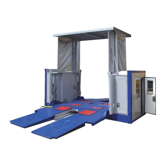
MTL 15
Mobile Test Container
Original Operating Instructions
BA022901-en
Pos: 1 / Te chnisc he Dokum entation/Bremsprüf tec hnik/MBT-SE RIES/022901
Mob ile Prüf tec hnik/022901_002
MTL 15 | M obiler Prüf conta iner/BA/Inhalt: 0229 Tite lbild @ 53\mod_ 1525240049974_0.docx @ 3032168 @ @ 1
Pos: 1 / Te chnisc he Dokum entation/Hebe tec hnik/08
S cheren-Hebeb ühnen/ 2901
DUO CM/BA/Inha lt: 0829 Tite lbild @ 42\m od_1436788474721_ 0.docx @ 2270230 @ @ 1
Pos: 2 /--- --Format---- -/MANUELLER UM BRUCH Seite numbruc h @ 0\mod_ 1134403577687_ 0.d ocx @ 1277 @ @ 1
Fehler! Verwenden Sie die Registerkarte 'Start', um Name dem Text zuzuweisen, der hier angezeigt werden soll.Fehler! Verwenden Sie
die Registerkarte 'Start', um Name dem Text zuzuweisen, der hier angezeigt werden soll.Fehler! Verwenden Sie die Registerkarte
'Start', um Name dem Text zuzuweisen, der hier angezeigt werden soll.
Advertisement
Table of Contents

Related Manuals for MAHA MTL 15


Summary of Contents for MAHA MTL 15
- Page 1 Pos: 1 / Te chnisc he Dokum entation/Bremsprüf tec hnik/MBT-SE RIES/022901 Mob ile Prüf tec hnik/022901_002 MTL 15 | M obiler Prüf conta iner/BA/Inhalt: 0229 Tite lbild @ 53\mod_ 1525240049974_0.docx @ 3032168 @ @ 1 Pos: 1 / Te chnisc he Dokum entation/Hebe tec hnik/08 S cheren-Hebeb ühnen/ 2901...
- Page 2 Pos: 3 / Te chnisc he Dokum entation/A lle Gerä te/Inhalte/Inha lt: Firmen-I nforma tion MAHA @ 53\mod_ 1529400378770_ 75.docx @ 3037518 @ @ 1 © MAHA Maschinenbau Haldenwang GmbH & Co. KG Legal notice based on ISO 16016: The reproduction, distribution and utilization of this document as well as the communication of its contents to others without explicit authorization is prohibited.
-
Page 3: Table Of Contents
Pos: 5 /--- --Format---- -/Inha ltsv erzeic hnis - 3 Ebe ne n @ 5\mod_ 1168867441046_ 75.docx @ 72920 @ @ 1 Contents Safety ........................5 Symbols and Signal Words ..................5 1.1.1 Personal Injury ......................5 1.1.2 Property Damage ..................... 5 1.1.3 Information ....................... - Page 4 Pos: 7 /--- --Format---- -/MANUELLER UM BRUCH Seite numbruc h @ 0\mod_ 1134403577687_ 0.d ocx @ 1277 @ @ 1 BA022901-en...
-
Page 5: Safety
Pos: 8 / Te chnisc he Dokum entation/A lle Gerä te/ Überschrif te n/Übersc hriften 1/S/ Überschrift 1: Sicherheit @ 6\mod_ 1174482399906_75.d ocx @ 76962 @ 1 @ 1 Safety Pos: 9 / Te chnisc he Dokum entation/A lle Gerä te/Inhalte/S ic herhe it/Inha lt: Einf ührung Sicher heit_ 12p t @ 25\mod_ 1324455248318_75.d ocx @ 1138886 @ @ 1 Thoroughly read this manual before operating the equipment and comply with the instructions. -
Page 6: Description
Pos: 13 / Tec hnische Dokume ntation/Bremsprüftec hnik/MBT-SERIE S/022901 M obile Prüftechnik/022901_ 002 M TL 15 | Mob iler Prüfc onta iner/BA/Inha lt: 0229 M TL 15 k omple tt @ 53\mod_ 1523944918725_ 75.docx @ 3028798 @ 12222222222211221 @ 1 Description General The test container is designed for 1-man operation and is set up in a ready-to-use... - Page 7 Contact between the frame and ramp, evenness The ramps may not be in contact with the bottom edge of the frame. Maximum permissible ramp angle relative to the frame: -5° Evenness if the mobile test container has ramps • Incline (horizontal) Maximum permissible deviation from the horizontal plane: ±1% Max.
-
Page 8: Overview
Overview Technical Data Dimensions Length 6,053 mm Width 2,437 mm Height 2,587 mm Weight (ready for operation) approx. 12,500 kg Fastening fittings for freight containers Standard ISO 1161 JOST CC297 TL, CC 298 TR Bottom JOST CC299 BL, CC 300 BR BA022901-en... - Page 9 Support feet System Electro-hydraulic with cable remote control Support feet lifting height 1,307 mm Min. drive-through width 2,590 mm (DIN 70014 and DIN EN 284) Greatest support equipment width 3,200 mm Greatest support equipment length 4,373 mm Test chamber (lifting roof) Drive-through width 3,625 mm Drive-through height, roof extended...
-
Page 10: Office
Office • 1-man office • Approx. 2 m² floor space • Desk • Lighting with light switch • 230 V electrical connections • Cashier window • Door lockable, insulated, incl. ventilation slots • Sliding door between office and test area •... -
Page 11: Protective Roof
Control and Display Elements 2.12.1 Operating Unit in the Office From top to bottom: • MAHA main switch (– Q1) for switching the MAHA test equipment on and off • <EMERGENCY OFF> mushroom button (red) • <MAINS ON> indicator light (white) •... -
Page 12: Cable Remote Control
2.12.2 Cable Remote Control <EMERGENCY OFF> mushroom button (red) The emergency off switch is used to quickly switch off the entire control if a hazard occurs. Once this button has been pressed, the <FAULT> indicator light lights up. The system’s ready for operation state is restored by turning the mushroom button to the right. -
Page 13: Operating Panel Connection Diagram
2.13 Operating Panel Connection Diagram Brake tester antenna Axle play tester antenna Radio receiver Roller heating Counter rotation Noise level meter Emission testers Simultaneous display BA022901-en... -
Page 14: Test Container Setup
Test Container Setup NOTICE • Before every commissioning operation, check that the raising and lowering range of both the container and the lifting roof the swivel range of the ramps and their drive elements are free from obstacles. •... - Page 15 NOTICE • Ensure under all circumstances that the connected mains supply has: three 230 / 400 V AC phases, one N neutral conductor, one PE ground conductor and one clockwise rotating field. • Ensure that the pin assignment is correct, otherwise the test container cannot be operated, because a phase monitoring relay is installed in the control cabi- net.
- Page 16 Drive the transport vehicle away without any contact under the container. Check the container’s lowering range again and remove any objects if necessary. DANGER • It is prohibited to remain underneath the raised container. • The container may only be raised for loading purposes. •...
- Page 17 b. Assemble all eight ramp rollers and secure with the safety splint. DANGER • Two people are required under all circumstances during the next work pro- cess. • When extending and retracting the ramps, it must be guaranteed that the op- erator holding the cable remote control can see the ramps actuated.
- Page 18 14 Raise the ramps with the pull lever, remove all the rollers and store them in a safe place. CAUTION In the joint area, the ramps must be firmly on the ground, otherwise driving onto the ramp is not permitted. 14 Extend all spindle supports (three per side) as far as the ground.
- Page 19 17 Switch off the main switch in the power unit compartment. 18 Unscrew the side slip tester’s transport lock screw and store it in a safe place. 19 Set up and connect the testers as required (also see the “Description > Operating Panel Connection Diagram”...
- Page 20 Acknowledge with the blue <RE- SET> pushbutton (B) on the remote control or in the office. 22 Switch on the MAHA main switch (C) in the test container’s office. 23 The door between the office and the test stand must be locked before testing the vehicle.
Need help?
Do you have a question about the MTL 15 and is the answer not in the manual?
Questions and answers