Table of Contents
Advertisement
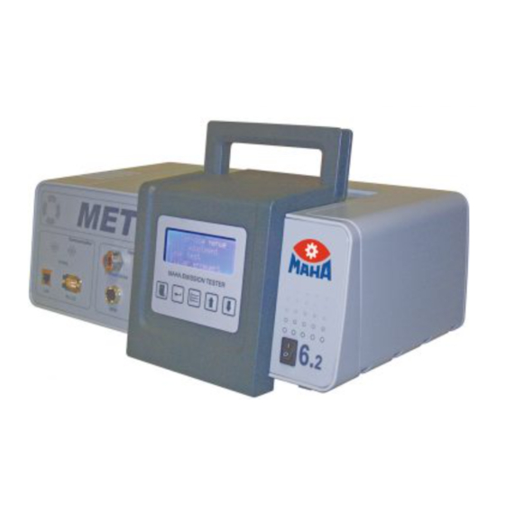
MET 6.1 | 6.2 | 6.3
Exhaust Gas Analyser | Opacimeter | Combination Tester
Original Operating Instructions
BA315001-en
Fehler! Verwenden Sie die Registerkarte 'Start', um Name dem Text zuzuweisen, der hier angezeigt werden soll.Fehler! Verwenden Sie
die Registerkarte 'Start', um Name dem Text zuzuweisen, der hier angezeigt werden soll.Fehler! Verwenden Sie die Registerkarte
'Start', um Name dem Text zuzuweisen, der hier angezeigt werden soll.
Advertisement
Table of Contents

Related Manuals for MAHA MET Series


Summary of Contents for MAHA MET Series
- Page 1 MET 6.1 | 6.2 | 6.3 Exhaust Gas Analyser | Opacimeter | Combination Tester Original Operating Instructions BA315001-en Fehler! Verwenden Sie die Registerkarte 'Start', um Name dem Text zuzuweisen, der hier angezeigt werden soll.Fehler! Verwenden Sie die Registerkarte 'Start', um Name dem Text zuzuweisen, der hier angezeigt werden soll.Fehler! Verwenden Sie die Registerkarte 'Start', um Name dem Text zuzuweisen, der hier angezeigt werden soll.
- Page 2 BA315001-en 2019-10-10 © MAHA Maschinenbau Haldenwang GmbH & Co. KG The reproduction, distribution and utilization of this document as well as the communication of its contents to others without explicit authorization is prohibited. Offenders will be held liable for the payment of damages. All rights reserved in the event of the grant of a patent, utility model or design.
-
Page 3: Table Of Contents
Contents Safety ........................5 Introduction ......................5 Symbols and Signal Words ..................5 1.2.1 Personal Injury ......................5 1.2.2 Property Damage ..................... 5 1.2.3 Information ....................... 5 Intended Use ......................6 Requirements on Operating and Service Personnel ..........6 Safety Instructions ....................7 Important User Information .................. - Page 4 9.14.1 Calibration at the Unit ..................... 37 9.14.2 Calibration via the MES ..................37 9.15 Spare Parts ......................38 9.16 Troubleshooting ..................... 39 Configuration Options via MAHA Emission Software ..........42 10.1 Company Information/Inspection Body ..............42 10.2 Exhaust Emission Inspection Number ..............42 10.3 Examiner List ......................
-
Page 5: Safety
Safety Introduction Thoroughly read this manual before operating the equipment and comply with the instructions. Always display the manual in a conspicuous location. Personal injury and property damage incurred due to non-compliance with these safety instructions are not covered by the product liability regulations. Symbols and Signal Words 1.2.1 Personal Injury... -
Page 6: Intended Use
Intended Use • The emission tester is intended exclusively for the sampling and analysis of vehicle exhaust gases. • The maximum exhaust gas temperature during use of the supplied probe is 250 °C. • The maximum exhaust gas temperature during use of the optionally available high-temperature probe is 750 °C. -
Page 7: Safety Instructions
Safety Instructions DANGER • Danger of burns on hot exhaust probe! Only hold the probe with the handle specifically intended for this purpose! • Danger of carbon monoxide poisoning from vehicle exhaust fumes! The oper- ator must ensure that any exhaust emission tests are only performed in spac- es with adequate exhaust gas extraction and ventilation. -
Page 8: Maintenance
Maintenance The MET 6.x must be serviced in accordance with the specifications given in the section entitled ‘Servicing’ and the servicing work must be documented in the servicing log. The following information must be recorded: • When servicing was performed •... -
Page 9: Scope Of Delivery
Operating manual with inspection log or servicing log Sampling probe with 200 cm tubing + 60 cm probe Seal tubing for leaktightness test Replacement O-ring, probe tubing coupling Replacement O-ring, water extractor Condensate catch tank MAHA Emission Software V7.51 with PIN code for activation BA315001-en... -
Page 10: Controls, Interfaces And Components
Controls, Interfaces and Components Front and Back View a: Exit (leave menu item) / Display with control buttons b: Confirm / c: Menu / d: Up in menu / e: Down in menu Master switch Coupling for sample gas probe Network connection, LAN port Port for speed sensor and oil temperature sensor Supply voltage 10 to 30 V;... -
Page 11: Side View
Side View Calibration gas inlet (not with MET 6.2) Opacimeter LED, transmitter (not with MET 6.1) Water extractor sensor (not with MET 6.2) Opacimeter sensor, receiver (not with MET 6.1) Filter F1; left side: water, right side: gas Filter F2 BA315001-en... -
Page 12: Description Of The Unit
To ensure that any official exhaust emission inspection that is performed is compliant with legal regulations, the unit must be operated via a PC with the corresponding MAHA Emission Software (MES). In such a case, the MET is operated from the PC. The software components for specific countries are described in separate operating instructions. -
Page 13: Basic Settings
Basic Settings Display Language Display: Menu > Set language Time MES: Otto or Diesel > Device diagnosis > Time/Date Display: Menu > Set time Date The unit's date setting is configured before delivery. In accordance with official calibration regulations, the date must not be altered by the end customer if the unit is used in connection with the regular technical vehicle inspection as per section 29 of the German Road Traffic Licensing Regulations (StVZO). -
Page 14: Zero Adjustment
Display: Menu > Servicing menu > Leaktightness test Zero Adjustment The MET checks whether zero-balance adjustment is necessary before each measurement. If the last zero-balance adjustment was performed more than 8 minutes ago, an adjustment is automatically performed before the measurement. This involves ambient air being induced through combined particle and activated carbon filter F2. -
Page 15: Measurement
Measurement When a measurement is started, the display shows the measurement values relevant for official calibrations in the top three lines, with additional information in the bottom line (the information line). You can use the arrow keys to access the following in the information line: •... -
Page 16: Initial Operation
"EUROSYSTEM Software for Exhaust Gas Analysers" (TIE10101_009), which is provided on the installation CD. Configuring the PC–MET and PC–MAHA VCI connections The establishment of the WiFi connection for configuring the MAHA VCI is described in the user manual “Establishing and Operating WiFi Networks” (BA315001_002). -
Page 17: Wifi Connection
Network configurations can be adjusted at the unit. Display: Menu > Network menu > LAN settings Connection Display The LAN connection status is shown in the display: > < Connection is being looked for >–< LAN connection established WiFi Connection As an option, the exhaust gas analyser and control PC can also be connected wirelessly via WiFi. -
Page 18: Maintenance
Maintenance Maintenance Schedule Servicing point Leaktightness test Every day, automatically After servicing work to the opacimeter or the water extractor Sampling probe and tubing Clean the sampling tubing Clean the sampling probe Cracks, abrasion points or pressure points on the *1 *1 tubing? Sampling probe clamp damaged? - Page 19 12 months at the latest to ensure trouble-free operation. *6 The battery (on the main board) is designed to have a service life of 12 years. MAHA recommends changing the battery after 10 years. The service life may BA315001-en...
-
Page 20: Cleaning The Sampling Probe And Tubing
be significantly shorter if climatic conditions are unfavourable (i.e. high humidity, extreme temperatures). Cleaning the Sampling Probe and Tubing Soot and condensate collects in the sampling tubing. These residues are removed as follows: Detach the sampling tubing from the unit. Use compressed air (5 bar max.) to blow out the tubing towards the exhaust probe until no more condensate and soot comes out. - Page 21 Open the filters under clean working conditions by turning the filter hous- ing anticlockwise. Open the filter clamp by carefully pulling it off and remove the filter in- sert. Check the filter clamp, filter holder and filter housing for dirt. If neces- sary, clean the affected parts with a dry, lint-free cloth.
- Page 22 Insert the new filter insert into the filter holder and fasten it with the fil- ter clamp. Fasten the filter housing by turning it clockwise thoroughly finger-tight on the filter housing. Re-insert the F1 filters. It must be ensured that the marking of the filter holder points upwards (12 o’clock position).
-
Page 23: Changing The Blue F1 And F2 Filters
10 Confirm in the device menu display: Menu > Service menu > Filter replaced > Filter F1 or Filter F2 MES: Menu diagnosis > Otto/Diesel diagnosis > Maintenance overview > Filter changed > Filter F1 or Filter F2 Changing the Blue F1 and F2 Filters Open the right-hand servicing hatch. -
Page 24: Cleaning The Opacimeter (Met 6.2 / 6.3) And Water Extractor
Cleaning the Opacimeter (MET 6.2 / 6.3) and Water Extractor BA315001-en... - Page 25 Transmitter/receiver of the opacimeter (unscrewed in illustration) Filter mount Bottom opening of the water extractor Quick-release coupling Upper right opening of the water extractor Opening of the measurement tube Upper left opening of the water extractor Middle borehole (O-ring) of right-hand F1 filter insertion As the internal tubing lines, the water extractor and the opacimeter are all subject to the same soiling, they should all be cleaned at the same time.
- Page 26 Procedure Switch the unit on and change to With the unit in measurement mode, "Measurement" mode. switch off the unit at the master switch so that the zero-balance valve remains in the measurement position. Remove the sampling tubing from the unit. BA315001-en...
- Page 27 Open the two servicing hatches. Fully unscrew the knurled screw to remove the cover of the water extractor. BA315001-en...
- Page 28 Remove the two F1 filters. Loosen the knurled nuts to remove the transmitter and receiver of the opacimeter. BA315001-en...
- Page 29 Hold a cloth in front of the openings of the filter mount. Blow compressed air into the bottom opening of the water extractor until no more impurities come out of the filter mount. Hold a cloth in front of the opening of the quick-release coupling. Blow air into the upper right opening of the water extractor until no more impurities come out.
- Page 30 10 Hold a cloth in front of the openings of the measurement tube. Blow air into the upper left opening of the water extractor until no more impurities come out. 11 Blow air into the middle borehole (O-ring) of the right-hand F1 filter insertion until no more impurities come of out the measurement tube.
- Page 31 12 Hold a cloth in front of the right-hand opening of the measurement tube and blow air into the left-hand opening until no more impurities come out of the right-hand opening. 13 Clean the surface of the water ex- 14 Clean the cover of the water extrac- tractor with a cloth.
- Page 32 15 Clean the sensor and receiver discs as required. 16 Mount the transmitter and the receiver. Ensure that the transmitter is correctly aligned to the bearing surface. BA315001-en...
- Page 33 17 Re-mount the F1 filters. 18 Put the cover of the water extractor back on and tighten the knurled screw until the edge of the cover makes contact with the surface. The screw then needs to be turned fur- ther, by one quarter of a rotation. BA315001-en...
-
Page 34: Water Extractor: Changing The O-Ring
19 Blow air into the sampling tubing in the direction of the probe. 20 Insert the sampling tubing. 21 Close the servicing hatches. 22 Switch the unit on and perform a leaktightness test. Water Extractor: Changing the O-Ring Fully unscrew the knurled screw to remove the cover of the water extractor. Remove the O-ring. -
Page 35: Probe Tubing Coupling: Changing The O-Ring
Probe Tubing Coupling: Changing the O-Ring Remove the probe tubing from the unit. Remove the O-ring from the nipple of the coupling. Important: Do not use a hard tool with sharp edges. Risk of damage! Insert the new O-ring into the groove. Re-attach the probe tubing. -
Page 36: Adjusting The Ir Test Bench (Met 6.1 / 6.3 Only)
Pressure regulator (part # 28000092) • Connection tubing suitable for 5 mm barbed fitting • MAHA Emission Software Procedure: Start the MET service tool via: MES: Otto > Device diagnosis > Adjustment Windows: Start Programs > Maschinenbau Haldenwang > EUROSYSTEM X.XX >... -
Page 37: Calibrating The Opacimeter (Met 6.2 / 6.3)
If the permissible deviation is exceeded during calibration, first clean the measurement tube, the transmitter and the receiver. If this does not correct the deviation, an error has occurred. In this case, please contact MAHA Service. UMBRUCH Seitenumbruch @ 0\mod_1134403577687_0.docx @ 1278 @@ 1 The length of the MET's measurement chamber is 287 mm. -
Page 38: Spare Parts
9.15 Spare Parts Name Order number Filter set 030460 00072 0 2 × filter F1 Servicing set, annual servicing 030460 00073 0 2 × filter F1 1 × filter F2 1 × O-ring probe tubing coupling 1 × O-ring water extractor Oxygen sensor 20 0410 BA315001-en... -
Page 39: Troubleshooting
9.16 Troubleshooting More than one error may occur at the same time. The unit only displays the most recent errors. A list of all errors that have occurred can be found in the servicing menu. Display: > Servicing menu > MET error codes Error Error/Error message Diagnosis/Corrective action... - Page 40 Error Error/Error message Diagnosis/Corrective action code You can acknowledge errors by clicking the ‘Confirm’ button. Measurement is possible, but be aware that there Water extractor faulty, is a high risk that the unit will fail! – Better: power consumption too high ...
- Page 41 Error Error/Error message Diagnosis/Corrective action code Are F1 filters mounted correctly? Is the cover of the water extractor open? Check filter; pump defective Master switch off, wait 10 s, master switch on. No improvement? Notify Service. Change both F1 filters. Filter blocked! Master switch off, wait 10 s, master switch on.
-
Page 42: Configuration Options Via Maha Emission Software
• Exporting measurement values and data • Backing up data • Calling up the contact data of the MAHA hotline 10.1 Company Information/Inspection Body MES: Otto or diesel > Device diagnosis > Address, place of inspection 10.2 Exhaust Emission Inspection Number MES: Otto or diesel >... -
Page 43: Optional Accessories
Optional Accessories 11.1 Carriage The carriage is able to hold all the system's components. 11.2 Mobility Kit For mobile use, the MET 6.x can be mounted in a transport case. BA315001-en... -
Page 44: Maha Vci
11.3 MAHA VCI The MAHA VCI and MAHA Emission Software can perform OBD diagnostics on vehicles (cars, LCVs, trucks and buses). Communication with the PC is wireless via WiFi. The VCI can be operated either as a WiFi base station (access point) or as a WiFi client, connected to the existing WiFi network. -
Page 45: On-Board Electrical System Cable
11.4 On-Board Electrical System Cable 11.5 Oil Temperature Sensor To document the oil temperature before the measurement, an oil temperature sensor can be connected to the MET 6.3. The value is then automatically recorded in the measurement log. 11.6 NO/NO Sensor For measuring the proportion of nitrogen oxide in the exhaust gas by means of two separate sensors: nitrogen oxide (NO sensor) and nitrogen dioxide (NO... -
Page 46: Rpm Counter
Disposal 12.1 Measurement Device If you want to dispose of the equipment, please contact your MAHA dealer or the following address, indicating equipment type, date of purchase and serial number: MAHA Maschinenbau Haldenwang GmbH & Co. KG Hoyen 20 | 87490 Haldenwang | Germany... -
Page 47: Specifications
Specifications Measurement properties Measured Measuring Measurement Principle of Response Resolution running variables range accuracy measurement time (T90) time 0 to 2 000 ±4 ppm abs. HC (hexane) or 3% rel. 0 to 4 000 ±8 ppm abs. or 3% rel. 1 ppm vol HC (propa- 4 001 to... - Page 48 OIML R99 class 0. Requirements The opacimeter meets the requirements of MessEV. This MAHA product is a high-quality meas- urement device that must not be disposed of Disposal with household waste. See the information given in the section entitled "Disposal".
-
Page 49: Sample Nameplate
= 0,1 m Contents of the Declaration of Conformity MAHA Maschinenbau Haldenwang GmbH & Co. KG herewith declares as a manufacturer its sole responsibility to ensure that the product named hereafter meets the safety and health regulations both in design and construction required by the EC directives stated below. - Page 50 MET 6 | Servicing Log Machine Company: owner Address: Servicing points Sampling probe Tubing checked for cracks, abrasion points and pressure points and tubing Sampling probe clamp checked for damage Protective cap on clamp support present Spacer at probe tip checked for damage O-ring of the probe coupling changed Heated sampling Functional test performed...
Need help?
Do you have a question about the MET Series and is the answer not in the manual?
Questions and answers