Table of Contents
Advertisement
Quick Links
Advertisement
Table of Contents
Troubleshooting

Related Manuals for MAHA MLT 3000 2.0


Summary of Contents for MAHA MLT 3000 2.0
- Page 1 MLT 3000 2.0 Headlight Tester Original Operating Instructions BA381001-en...
- Page 2 MAHA's claim is to also be a leader in the areas of reliability, safety and sustainability – this can be seen in many details that have been developed with these aspects in mind.
-
Page 3: Table Of Contents
Contents General Safety Instructions ..........................5 Introduction ..............................5 Symbols and Signal Words ......................... 5 1.2.1 Personal Injury ............................5 1.2.2 Property Damage ..........................5 Requirements on Operating and Service Personnel .................. 6 Intended Use ..............................6 Description ............................... 6 General Information ............................. - Page 4 4.6.8 Selecting a Language .......................... 26 EUROSYSTEM Settings ..........................27 Service Menu ............................. 29 4.8.1 Country-Specific Defaults ........................29 Energy Management and Troubleshooting ....................30 Charging the Battery ..........................30 Battery Status ............................31 5.2.1 Battery Life ............................31 5.2.2 Display of Charge Level ........................
-
Page 5: General Safety Instructions
General Safety Instructions Introduction Thoroughly read this manual before operating the equipment and comply with the instructions. Always display the manual in a conspicuous location. Personal injury and property damage incurred due to non-compliance with these safety instructions are not covered by the product liability regulations. Symbols and Signal Words 1.2.1 Personal Injury... -
Page 6: Requirements On Operating And Service Personnel
Any infringement renders the conformity declaration invalid. Description General Information The MLT 3000 2.0 digital headlight tester is used to quickly and objectively check and adjust vehicle headlights. It takes into account all statutory limits and any OEM specifications. -
Page 7: Technical Data
Technical Data Measuring range above hotspot ........ 0…800 mm / 10 m (0…8 %) above pitch angle ......0…300 mm / 10 m (0…3 %) below ..........0…700 mm / 10 m (0…7 %) left..........0…1000 mm / 10 m (0…10 %) right ..........0…1000 mm / 10 m (0…10 %) Light intensity .................. -
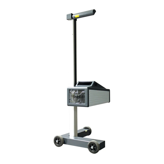
Page 8: Overview With Components
Overview with Components Laser alignment unit Charging socket Column USB port Display Casing, with push handle Battery compartment Chassis BA381001-en... -
Page 9: Electronic Levelling
Electronic Levelling This headlight tester comes standard with an electronic position sensor which determines the inclination angle of the device. The software compensates possible deviations in the X- and Z-axes while calculating the position of the headlights. The headlight tester may be set up on uneven surfaces even if the ground unevenness is outside the permissible tolerances, provided that the maximum unevenness does not exceed the headlight tester’s self-levelling capacity of 3%. -
Page 10: Angle Symbols
2.5.2 Angle Symbols Once the adjustment of the inclination sensor has been completed, an angle symbol appears in the info bar to indicate the adjusted/active inclination axes. Overview of symbols: Both axes adjusted/active, Z-axis active, headlight headlight tester ready for tester ready for operation operation Both axes active, inclination... -
Page 11: Low Beam
2.6.2 Low Beam A Light-dark limit Boundary of light distribution between ‘top dark’ and ‘bottom light’ for low- beam lights. B Inflection point Inflection point of light-dark limit for asymmetric low-beam lights. The deviation of the inflection point is expressed in percentage. ... -
Page 12: Si Units Of Brightness
specified in percentage or optionally in angular minutes. ‘I’ indicates the illuminance in Lux or optionally the light intensity in Candela in the area of the central mark. D Hot spot Centre of light beam for high-beam. The deviation of the hot spot from the central mark is expressed in percentage. -
Page 13: Operation
Operation Safety Instructions NOTICE • The device may only be operated within its performance limits. • All parts of the electrical system must be protected against damp and humi- dity. • Never expose the lens to direct sunlight. The bundling of light may cause fire damage inside the casing. -
Page 14: Aligning The Headlight Tester
Aligning the Headlight Tester USB-C Sensor button CAUTION Never look into the laser beam (laser class 2M). Comply with work safety and accident prevention directives (H&SW regulations) in respect of laser radiation. 1 When using guide rails, position the headlight tester centrally in front of the vehicle. -
Page 15: Selection Buttons: Icon Description
• The laser can also be used during the charging process. Selection Buttons: Icon Description 4.4.1 Main Menu Tap the MAHA logo to open the service menu. User settings Headlight test according to § 29 StVZO (Germany) Original Equipment Manufac-... -
Page 16: Manufacturer-Specific Headlight Settings (Oem)
4.4.2 Manufacturer-Specific Headlight Settings (OEM) Button ALL makes several measurement levels available. Use the Down button to navigate through the measurement levels. INFO OEM section! Carry out the test according to manufacturer’s instructions. Performing a Headlight Test Main menu > Paragraph icon > Target values To start the measurement, press the desired light button. -
Page 17: Measuring Menu: Zoom Function
PA = Pitch angle IP = Inflection point I = Intensity in lux G = Glare * Display of Yaw and Roll angle can YawAngle * be additionally activated under ‘User RollAngle * settings > Meas. Value Angles’. New vehicle, measurement values are discarded Switchover to continuous measurement: image is permanently re-evaluated Switchover to static measurement:... -
Page 18: Measuring Menu: Manual Inflection Point Function
4.5.2 Measuring Menu: Manual Inflection Point Function If the inflection point is incorrectly or not recognised (red arrows to the left and right), the inflection point can be set manually. Press this button to activ- ate the manual inflection point function. The inflection point can be set by tap- ping the touch display in the area of the light image. -
Page 19: Saving The Measurement Values To Pdf
Using the Up/Down buttons, the target value can be adjusted in the range from –1.0% to –1.2%. Button shows/hides the corridor for the cut-off line and the limit markings for the inflection point. Button shows/hides the cut-off line and the result values for pitch angle and inflection point. -
Page 20: Led Adjustment Aid (Option)
4.5.5 LED Adjustment Aid (Option) This optional unit is integrated into the window casing (A) above the Fresnel lens. The colour LEDs (B) pointing toward the vehicle indicate the direction of adjustment. Green LED = Optimum setting (corresponds to green evaluation in the display centre) Yellow LED = Minor deviation within tolerance range (corresponds to yellow direction arrows on the display) Red LED =... -
Page 21: User Settings
Software update MLT 3000/3000V2 via USB stick Battery status check Date/time adjustments AD converter values (inclination, temperature, battery voltage/ current) By tapping the flag button, additional languages are displayed for selection. 4.6.1 User Settings Enables access to the most important functions. Choose unit of intensity. - Page 22 If the headlight tester is moved while the battery is being charged, Signal warning a warning is issued on the display. Activates measurement of low-beam glare. Glare active USA (SAE) Switch over to evaluation according to SAE standard (VOR/VOL). headlights Show angle Activates determination of yaw and roll angle.
-
Page 23: User Variables
Choose vehicle manufacturers to be available in OEM menu. 4.6.2 User Variables Enter user name ‘user’ and password ‘0000’ to open the variable settings. Tap button ‘Variable settings’ to open them. All variables can be viewed, but changes are only possible for the ‘User variables’. -
Page 24: Pc Connection Via Bluetooth
4.6.3 PC Connection via Bluetooth • Wireless connection via Bluetooth, MAHA order number: VZ 990312 • Using these interfaces, a connection can be established with MAHA‘s EU- ROSYSTEM software (only in conjunction with V7.50.xxx or higher). Download available at: https://www.maha.de/en/software/downloads A Bluetooth stick must be connected to the headlight tester for the button to be visible. -
Page 25: Software Update
4.6.4 Software Update Software updates are performed using a USB stick (FAT32). Procedure: 1 Download the software update from the MAHA website: https://www.maha.de/en/software/downloads 2 Start the exe file and choose the USB stick. 3 Click on ‘Unpack’, then verify that folder ‘maha’... -
Page 26: Checking The Battery Status
4.6.5 Checking the Battery Status Possibility to check • Charging and battery voltage • Current from battery (negative val- • Current to battery (positive value) 4.6.6 Setting Date and Time Date and time settings can be corrected here. 4.6.7 Reading the AD Converter Values Specific raw values of the AD converters can be viewed here. -
Page 27: Eurosystem Settings
EUROSYSTEM Settings EUROSYSTEM connection: After the connection has been estab- lished, the yellow indicator lamp is ON. A Bluetooth symbol appears in the info bar of the headlight tester. Set variables using ‘System’ > ‘Settings’ > ‘Section, Lanes, External Devices’ Var. - Page 28 An overview of the measurement values appears. Select the desired measurement. The selected measurement data is displayed in detail. Adjusting the headlights: Use the camera button on the head- light tester display to switch over to headlight adjustment. EUROSYSTEM shows the coordinates, the measurement values and the head- light image in real time.
-
Page 29: Service Menu
Service Menu Open the Service menu by tapping the MAHA logo in the Main menu. Adjust inclination sensor: “Menu item accessible with technician password only” Camera adjustment: “Menu item accessible with technician password only” Without password entry, compensation values can be only reviewed using button “Calibrate camera according to... -
Page 30: Energy Management And Troubleshooting
Energy Management and Troubleshooting Charging the Battery The charger plug is plugged into the round hollow plug socket on the side of the housing (see illustration). If the ‘cable connection’ option (VZ 990312) is installed, the power supply and data transmission take place via the XLR plug on the underside of the SEP. In this case, the hollow plug socket is not connected. -
Page 31: Battery Status
Battery Status 5.2.1 Battery Life The battery has a nominal capacity of 13,400 mAh and allows up to 15 hours of continuous operation in the workshop at an optimum ambient temperature of 20 °C. 5.2.2 Display of Charge Level The charge level is calculated via the current drawn or supplied. This function is only available once the battery has been fully charged, as the actual battery capacity must be determined by the electronics. -
Page 32: Data Recording For Error Analysis
Data Recording for Error Analysis To record this data, a USB stick is required, which is plugged into the USB-A socket on the outside of the housing. INFO When recording is active, the device does not switch off automatically after 2 hours. -
Page 33: Maintenance
To ensure safe and reliable operation, only use original spare parts supplied by the equipment manufacturer. Disposal If you want to dispose of the equipment, please contact your MAHA dealer or the following address, indicating equipment type, date of purchase and serial number: MAHA Maschinenbau Haldenwang GmbH &... -
Page 34: Declaration Of Conformity
Declaration of Conformity See following page(s). BA381001-en... - Page 35 Ralf Kerkmeier, MAHA Maschinenbau Haldenwang GmbH & Co. KG, Hoyen 20, 87490 Haldenwang, Germany Haldenwang, 2024-12-01 Dr. Peter Geigle Geschäftsführer | Managing Director MAHA Maschinenbau Haldenwang GmbH & Co. KG · Hoyen 20 · 87490 Haldenwang · Germany ☎ +49 8374 585-0 · maha@maha.de · www.maha.de...
- Page 36 PL670000_002-de...
Need help?
Do you have a question about the MLT 3000 2.0 and is the answer not in the manual?
Questions and answers