Xilinx ML505 Getting Started Tutorial
Evaluation platforms
Hide thumbs
Also See for ML505:
- Quick start manual (29 pages) ,
- Quick start manual (41 pages) ,
- User manual (60 pages)

Related Manuals for Xilinx ML505


Summary of Contents for Xilinx ML505
- Page 1 ML505/ML506/ML507 Getting Started Tutorial For ML505/ML506/ML507 Evaluation Platforms UG348 (v3.0.2) October 9, 2008 PN 0402745-01 www.BDTIC.com/XILINX...
- Page 2 Xilinx. Xilinx expressly disclaims any liability arising out of your use of the Documentation. Xilinx reserves the right, at its sole discretion, to change the Documentation without notice at any time. Xilinx assumes no obligation to correct any errors contained in the Documentation, or to advise you of any corrections or updates.
-
Page 3: Table Of Contents
Setup Web Server (ML505/ML506 - Using Soft Ethernet MAC IP Core) ....16 ............. 16 Location . - Page 4 ..............31 www.BDTIC.com/XILINX www.xilinx.com ML505/ML506/ML507 Getting Started Tutorial UG348 (v3.0.2) October 9, 2008...
-
Page 5: Preface: About This Guide
About This Guide The ML505/ML506/ML507 Getting Started Tutorial provides step-by-step instructions for setting up and using the Virtex®-5 FPGA ML505, ML506, and ML507 Evaluation Platforms (referred to as the ML50x board in this guide). The ML50x board comes with a number of pre-installed demonstrations. -
Page 6: Additional Support Resources
PCB and interface level. Additional Support Resources To search the database of silicon and software questions and answers, or to create a technical support case in WebCase, see the Xilinx website at: http://www.xilinx.com/support. www.BDTIC.com/XILINX www.xilinx.com... -
Page 7: Typographical Conventions
Cross-reference link to a location Figure 2 in the Virtex-5 Data Red text in another document Sheet Go to http://www.xilinx.com Blue, underlined text Hyperlink to a website (URL) for the latest documentation. www.BDTIC.com/XILINX ML505/ML506/ML507 Getting Started Tutorial www.xilinx.com UG348 (v3.0.2) October 9, 2008... - Page 8 Preface: About This Guide www.BDTIC.com/XILINX www.xilinx.com ML505/ML506/ML507 Getting Started Tutorial UG348 (v3.0.2) October 9, 2008...
-
Page 9: Ml505/Ml506/Ml507 Getting Started Tutorial
ML505/ML506/ML507 Getting Started Tutorial Overview The ML505, ML506, and ML507 Evaluation Platforms (referred to as ML50x boards in this guide [Ref 1]) come with a number of pre-installed demonstrations [Ref 2]. This tutorial guides you through these demonstrations and provides instructions to run them on ML50x boards. -
Page 10: Board Setup
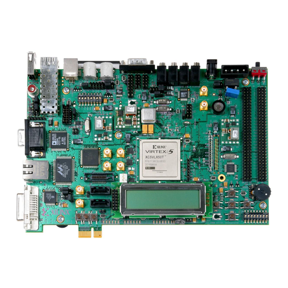
Board Setup Board Setup Position the ML50x board so the Xilinx logo is in the lower left corner. Make sure the power switch located in the upper right corner is in the OFF position. Locate the CF card slot (on the back side of the ML50x board), and carefully insert the System ACE™... - Page 11 In the 9600-HyperTerminal window, select File → Properties ♦ Select the Connect To tab Select COM1 in the Connect using box (see Figure Click Configure... UG348_03_040408 Figure 3: HyperTerminal Setup and Properties www.BDTIC.com/XILINX ML505/ML506/ML507 Getting Started Tutorial www.xilinx.com UG348 (v3.0.2) October 9, 2008...
- Page 12 Click OK → OK to accept settings ♦ UG348_04_040408 Figure 4: COM1 Properties Setup Select File → Properties. Select the Settings tab and click on ASCII Setup (Figure 5, page 11). www.BDTIC.com/XILINX www.xilinx.com ML505/ML506/ML507 Getting Started Tutorial UG348 (v3.0.2) October 9, 2008...
- Page 13 Unzip the training lab files to a working directory, name the directory, and make note of the directory’s name. This directory with the extracted files is referred to as <LAB_DIR> in this tutorial. www.BDTIC.com/XILINX ML505/ML506/ML507 Getting Started Tutorial www.xilinx.com UG348 (v3.0.2) October 9, 2008...
-
Page 14: Ml50X Demonstrations In System Ace Cf
The demonstrations are: • “Virtex-5 FPGA Slide Show,” page 15 • “Web Server (ML505/ML506 - Using Soft Ethernet MAC IP Core),” page 16 • “Web Server (ML507 - Using Integrated Tri-Mode Ethernet MAC Block),” page 18 • “Simon Game,” page 20 •... -
Page 15: Virtex-5 Fpga Slide Show
For audio, try to extract a song from a CD into a WAV file. Copy the WAV file into the System ACE CF card and name it sound.wav. www.BDTIC.com/XILINX ML505/ML506/ML507 Getting Started Tutorial www.xilinx.com UG348 (v3.0.2) October 9, 2008... -
Page 16: Web Server (Ml505/Ml506 - Using Soft Ethernet Mac Ip Core)
Web browser causes the background color to change and the current DIP switch values to be re-read. By default, the IP address of the ML505 and ML506 boards is 1.2.3.4, but it can be changed by recompiling the software. - Page 17 ♦ On the remote computer host, you can ping 1.2.3.4 to confirm that the network connection is alive. Restore your computer's network settings when finished. www.BDTIC.com/XILINX ML505/ML506/ML507 Getting Started Tutorial www.xilinx.com UG348 (v3.0.2) October 9, 2008...
-
Page 18: Web Server (Ml507 - Using Integrated Tri-Mode Ethernet Mac Block)
Right-click My Network Places on your computer, and select Properties ♦ Right-click Local Area Connection, and select Properties ♦ Select Internet Protocol (TCP/IP), and click Properties (Figure UG348_11_051408 Figure 9: Local Area Connection Properties Setup www.BDTIC.com/XILINX www.xilinx.com ML505/ML506/ML507 Getting Started Tutorial UG348 (v3.0.2) October 9, 2008... - Page 19 ♦ On the remote computer host, you can ping 192.168.1.10 to confirm that the network connection is alive. Restore your computer's network settings when finished. www.BDTIC.com/XILINX ML505/ML506/ML507 Getting Started Tutorial www.xilinx.com UG348 (v3.0.2) October 9, 2008...
-
Page 20: Simon Game
If a mistake is made, the score resets to 0 on the screen, the high score is updated, and all the LEDs blink rapidly to signify a new game. www.BDTIC.com/XILINX www.xilinx.com ML505/ML506/ML507 Getting Started Tutorial UG348 (v3.0.2) October 9, 2008... -
Page 21: Board Verification Using Xrom
7. Test PS/2 Keyboard 8. Test SMA Connectors 9. Test VGA Output A. Test Flash Memory B. Print IIC EEPROM Contents C. Test Piezo 0. Return to the Main Menu www.BDTIC.com/XILINX ML505/ML506/ML507 Getting Started Tutorial www.xilinx.com UG348 (v3.0.2) October 9, 2008... -
Page 22: Usb
Connect a standard USB keyboard to the ML50x board. Keys typed on the USB keyboard are then displayed on the character LCD and serial port. Note: This demonstration requires a USB keyboard without a built-in hub. www.BDTIC.com/XILINX www.xilinx.com ML505/ML506/ML507 Getting Started Tutorial UG348 (v3.0.2) October 9, 2008... -
Page 23: My Own Ace File
Bootloader. Select Option 6 to start the My own ACE file program. In this design, flipping a GPIO DIP switch or pressing a GPIO button will light a corresponding LED. www.BDTIC.com/XILINX ML505/ML506/ML507 Getting Started Tutorial www.xilinx.com UG348 (v3.0.2) October 9, 2008... -
Page 24: Ring Tone Player
Replace the User.txt file on the CF card with the RTTTL code (Option 7) ♦ With a serial terminal program, paste or type in the RTTTL code (Option 8) UG348_09_040408 Figure 11: RTTTL Setup www.BDTIC.com/XILINX www.xilinx.com ML505/ML506/ML507 Getting Started Tutorial UG348 (v3.0.2) October 9, 2008... -
Page 25: Rtttl Specification
Options field. If unspecified, these parameters take on the default value of the Options field. The extend duration parameter (a dot) defines a dotted note and lengthens the duration by 50 percent. www.BDTIC.com/XILINX ML505/ML506/ML507 Getting Started Tutorial www.xilinx.com UG348 (v3.0.2) October 9, 2008... -
Page 26: Ml50X Demonstrations In Linear Flash
This directory with the extracted files is referred to as <LAB_DIR> in this tutorial. In EDK, open the ml505_bsb_system.xmp project file. Open a Xilinx Cygwin Shell. From the EDK GUI menu, select Project → Launch EDK Shell Copy the BIT file destined for the linear flash to <LAB_DIR>. - Page 27 Configuration 0: 00001001 Configuration 1: 00101001 Configuration 2: 01001001 Configuration 3: 01101001 Press the PROG pushbutton to configure the Virtex-5 FPGA from the linear flash using the configuration selected in step www.BDTIC.com/XILINX ML505/ML506/ML507 Getting Started Tutorial www.xilinx.com UG348 (v3.0.2) October 9, 2008...
-
Page 28: Ml50X Demonstrations In Platform Flash
To select configuration using Platform Flash, set the configuration address and mode DIP switch (8-position DIP switch) to 00011001. Platform Flash LCD Demonstration Location ML505/ML506: Platform Flash configuration address 0. ML507: Platform Flash configuration address 1. Description This demonstration displays to the character LCD the message “Put Your Design Here”. -
Page 29: My Own Platform Flash Image Demonstration
Copy <file_name>.bit . Format the BIT file to an MCS file. For an ML505 (or ML506) board, on one line type in the command prompt: promgen -w -p mcs -c FF -o ml505_production_platflash -ver 0 my_plat_flash.bit -ver 1 xrom.bit -ver 2 <file_name>.bit -ver 3 <file_name>.bit -x xcf32p xcf32p... -
Page 30: Ml50X Demonstrations In Spi Flash
Disconnect the cable attached to header J1 (the header on the left side of the board) from the Xilinx download cable. Connect JTAG flying wires from the Xilinx download cable to the J2 header using the pin labels as a guide on how to make the connections. The 7-pin J2 header is located to the right of the FPGA and just above the LCD panel. -
Page 31: References
16. Press the Prog button. The design takes about 8 seconds to finish loading and begin to run. References Documents specific to the ML50x Evaluation Platform: , ML505/ML506/ML507 Evaluation Platform User Guide. UG347 UG349, ML505/ML506/ML507 Reference Design User Guide. Lab Resources: ML505, ML506, ML507.
Need help?
Do you have a question about the ML505 and is the answer not in the manual?
Questions and answers