JUKI AMB-289 Engineer's Manual
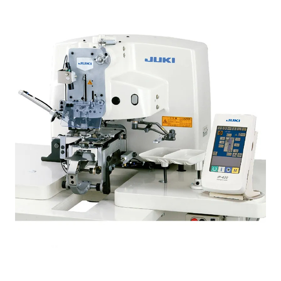
Computer-controlled, high-speed, single thread, chainstitch, button-neck-wraping machine
Hide thumbs
Also See for AMB-289:
- Instruction manual (119 pages) ,
- Handbook (257 pages) ,
- Engineer's manual (171 pages)

Subscribe to Our Youtube Channel
Related Manuals for JUKI AMB-289


Summary of Contents for JUKI AMB-289
- Page 1 ® Computer-controlled, High-speed, Single thread, Chainstitch, Button-neck-wraping Machine AMB-289 ENGINEER’S MANUAL 40020579 No.E365-01...
- Page 2 PREFACE This Engineer’s Manual is written for the technical personnel who are responsible for the service and maintenance of the machine. The Instruction Manual for these intended machines for the maintenance personnel and operators at an apparel factory contains operating instruction in derail. And this manual describes “Standard Adjustment”, “Adjustment Procedures”, “Results of Improper Adjustment”, and other important information which are not covered by the Instruction Manual.
-
Page 3: Table Of Contents
CONTENTS 1. Specifications ......................1 (1) Specifications ......................... 1 (2) Shapes of buttons ........................2 2. CONFIGURATION ....................4 (1) Sewing machine........................4 (2) Operation panel ........................5 3. STANDARD ADJUSTMENT ..................8 (1) Adjusting the height of the needle bar ................. 8 (2) Adjusting the clearance between the needle and the looper .......... - Page 4 6. SETUP OF IP-200 ....................86 (1) Connecting procedure of operation panel with external vehicle ........86 (2) Setup of operation panel...................... 90 (3) Setup of main program ......................93 (4) Setup of servo program ....................... 99 (5) When using smart media other than that which has been packed together ....105 (6) Formatting ...........................
-
Page 5: Specifications
1.Grease tube : 13525506 (containing 10g, green) for gear section of rack of the like and cam section 2.JUKI grease B tube : 40013640 (containing 10g, white) for worm section 3.JUKI grease A tube : 40006323 (containing 10g, white) for other rocking mechanism section to which lubrication is necessary Thread take-up level... -
Page 6: Shapes Of Buttons
(2) Shapes of buttons 1) Specifications for 4-holed and 2-holed buttons A : Buttonhole diameter Needle used : ø 1.5 mm or more when using #12 to #16 Needle used : ø 2 mm or more when using #16 to #18 B : Distance between buttonholes 1.5 to 6.0 mm (in increments of 0.1 mm) C : Location of buttonholes... - Page 7 3) Specifications for stay button Commendable dimension (Caution) 1. Outside Buttonhole Buttonhole Thickness 1mm or less diameter diameter pitch of button Type A 8.5mm 2.5mm 3.1mm 2.0mm Buttonhole Type B 10.2mm 3.2mm 4.0mm 2.0mm diameter Right side (Caution) 1. For the stay buttons, use those, the amount of convex on the right side of which is 1 mm or less.
-
Page 8: Configuration
2. CONFIGURATION (1) Sewing machine AMB-289 consists of the following components. Power ON/OFF switch Machine head(AMB-289) Operation panel(IP-200D) Control box(MC-640) Foot pedal Start switch Thread stand device – 4 –... -
Page 9: Operation Panel
(2) Operation panel 1) Body Touch panel • LCD display section READY key → Changeover of the data input screen and the sewing screen can be performed. INFORMATION key → Changeover of the data input screen and the information screen can be performed. - Page 10 2) Buttons to be used in common The buttons which perform common operations in each screen of IP-200 are as follows : CANCEL button → This button closes the pop-up screen. In case of the data change screen, the data being changed can be cancelled. ENTER button →...
- Page 11 MEMO – 7 –...
-
Page 12: Standard Adjustment
3. STANDARD ADJUSTMENT (1) Adjusting the height of the needle bar Standard Adjustment To align Marker line (2) Adjusting the clearance between the needle and the looper Standard Adjustment To align 0.05 to 0.1mm – 8 –... - Page 13 (Caution) Adjust the needle at the position of center (aligns with the engraved marker line on the machine bed). [Needle list] JUKI Part No. Needle Part No. Remarks MSM3AAN1100...
-
Page 14: Adjusting The Needle And The Needle Guide
(3) Adjusting the needle and the needle guide Standard Adjustment [The position of the needle and the throat plate] [The clearance between the needle and the needle guide] Center 0 to 0.1mm (4) Adjusting the position of the york slide Standard Adjustment Approx. - Page 15 Adjustment Procedure Results of Improper Adjustment o Stitch skipping, thread breakage, Adjusting the position of the needle and the throat plate or defective thread trimming 1. Loosen screws and adjust the throat plate so that the needle (trimming failure and two-thread enters the center of the needle hole.
-
Page 16: Wiper Adjustment
(5) Wiper adjustment Standard Adjustment [Wiper components] 3 to 5mm 6 to 8mm – 12 –... - Page 17 Adjustment Procedure Results of Improper Adjustment Assembling adjustment 1. Temporarily tighten the wiper at the position where cap nut is tight- ened to wiper cylinder rod 2. Fix wiper guide so that wiper guide and wiper equally come in contact with each other within the range of the stroke of cylinder 3.
-
Page 18: Adjusting The Face Plate Thread Tension
(6) Adjusting the face plate thread tension Standard Adjustment 12mm – 14 –... - Page 19 Adjustment Procedure Results of Improper Adjustment 1. Adjust face plate thread tension cylinder so that a clearance is o Face plate thread tension fails to opened between the face plate thread tension cylinder and tension work unless there is a clearance. release plate in the state that the air is drawn out.
-
Page 20: Adjusting The Cloth Presser Cylinder For Sewing Flat Button Directly To Cloth
(7) Adjusting the cloth presser cylinder for sewing flat button directly to cloth Standard Adjustment – 16 –... - Page 21 Adjustment Procedure Results of Improper Adjustment 1. Loosen cylinder nut , turn cylinder knuckle and adjust so that o When the height of cloth presser the top surface of the top end of cloth presser for sewing flat button for sewing flat button directly directly to cloth is 18.5 ±...
-
Page 22: Adjusting The Position Of Y Top Feed Motor
(8) Adjusting the position of Y top feed motor Standard Adjustment – 18 –... - Page 23 Adjustment Procedure Results of Improper Adjustment o When pressing is insufficient, 1. Loosen four setscrews , lightly press Y top feed motor in the backlash becomes large, and direction of arrow mark, and tighten four setscrews again, while pressing is excessive, torque moving the top feed unit to and fro and confirming that it smoothly becomes large.
-
Page 24: Adjusting The Position Of Y Bottom Feed Motor
(9) Adjusting the position of Y bottom feed motor Standard Adjustment – 20 –... - Page 25 Adjustment Procedure Results of Improper Adjustment 1. Loosen four setscrews , lightly press Y bottom feed motor in the o When pressing is insufficient, direction of arrow mark, and tighten four setscrews again, while backlash becomes large, and moving the top feed unit to and fro and confirming that it smoothly pressing is excessive, torque moves within the movable range.
-
Page 26: Adjusting The Tongue Up/Down Cylinder
(10) Adjusting the tongue up/down cylinder Standard Adjustment 19mm Gauge – 22 –... - Page 27 Adjustment Procedure Results of Improper Adjustment 1. Lower the tongue section, and tighten cylinder nut at the position where side face plates on both sides ride on rollers and rollers turn when tongue section is moved to and fro. 2. Loosen stopper setscrew and adjust so that the clearance be- o Button size is set up to 32 mm, tween the top surfacre of throat plate and tongue stopper...
-
Page 28: Adjusting The Chuck Up/Down Motor
(11) Adjusting the chuck up/down motor Standard Adjustment The centers almost align with each other. 0~0.5mm (0~0.1mm) – 24 –... - Page 29 Set the amount of backlash to 0.1 to 0.3 mm. 3. Apply enough JUKI grease B tube (white grease) to the whole teeth o When the position is improper, section after cleanly wiping white grease gathered around teeth of error occurs.
-
Page 30: Adjusting The Differential Feed (X Top Feed) Motor
(12) Adjusting the differential feed (X top feed) motor Standard Adjustment 6 ± 0.5mm Align – 26 –... - Page 31 Adjustment Procedure Results of Improper Adjustment 1. Loosen the four screws , move the rack gear shaft from side to o When pressing is insufficient, side while the differential feed (X top feed) motor is slightly pressed backlash becomes large, and in the arrow direction.
-
Page 32: Adjusting The Tongue Stopper
(13) Adjusting the tongue stopper Standard Adjustment [Tongue components] Tongue Cloth marker line Cloth – 28 –... - Page 33 Adjustment Procedure Results of Improper Adjustment 1. Align engraved line of the machine bed with the center of tongue stopper guide A . Slide the guide on the top of the tongue stopper mount bases until the guide contacts with end projections , and tighten the setscrews 2.
-
Page 34: Adjusting The Chuck Inversion Cylinder
(14) Adjusting the chuck inversion cylinder Standard Adjustment 22 ± 0.5mm Horizontal 15mm Vertical – 30 –... - Page 35 Adjustment Procedure Results of Improper Adjustment 1. To remove chuck inversion cylinder , remove hinge screw knuckle , cylinder and two setscrews 2. In the state that the button chuck is level, loosen nut and adjust so that the clearance between knuckle and cylinder is 22 ±...
-
Page 36: Adjusting The Chuck Open/Close Cylinder
(15) Adjusting the chuck open/close cylinder Standard Adjustment – 32 –... - Page 37 Adjustment Procedure Results of Improper Adjustment o When the sensor is set to ON 1. To remove sensor , remove two setscrews without holding the button, the 2. Fix sensor with setscrew at the position where sensor system recognizes that the button returned to the front by 0.5 to 1 mm from the position where sensor is held, and proceeds to the next lights and goes off at the position where the chuck fully closes in...
-
Page 38: Adjusting The Respective Sensors
(16) Adjusting the respective sensors (1/3) Standard Adjustment To align with engraved marker line on the machine bed marker line – 34 –... - Page 39 Adjustment Procedure Results of Improper Adjustment 1) Adjusting the needle throwing motor origin sensor 1. After assembling the needle throwing components, turn ON the power to display K51 of level 2 of the memory switch. (At this time, set the parameter display to “0”.) 2.
- Page 40 (16) Adjusting the respective sensors (2/3) Standard Adjustment 0~0.5mm (0~0.1mm) 29.5mm Center of needle Looper thread guide Thread guide Thread lightly touches. – 36 –...
- Page 41 Adjustment Procedure Results of Improper Adjustment 4) Adjusting the top feed sensor in the vertical direction 1. Set the button gauge supplied with the chuck as accessories. 2. Display K57 of level 2 of the memory switch. (At this time, set the parameter display to “0”.) 3.
- Page 42 (16) Adjusting the respective sensors (3/3) Standard Adjustment 14.5 ± 0.5mm – 38 –...
- Page 43 Adjustment Procedure Results of Improper Adjustment 7) Origin compensation at bottom feed going up (Perform adjustment after ensurng that the needle throwing motor origin and bottom feed motor origin have been adjusted.) 1. Call up K55 in memory switch level 2. 2.
-
Page 44: Disassembling, Assembling And Adjustment
4. DISASSEMBLING, ASSEMBLING AND ADJUSTMENT (1) Disassembling and assembling of the main shaft (1/2) Procedures of disassembling / assembling Setscrew ∗ ∗ ∗ Counterweight is a set of components. – 40 –... - Page 45 Procedures of disassembling / assembling Caution in disassembling / assembling Disassembling of the main shaft 1. Remove needle, rear cover , arm cover and face plate “refer to (2) Disassembling and assembling of the face plate”. 2. When timing belt is not replaced, put marking with white paint or o At the time of assembling, timing the like on main shaft sprocket...
-
Page 46: Disassembling And Assembling Of The Main Shaft
(1) Disassembling and assembling of the main shaft (2/2) Procedures of disassembling / assembling ∗ ∗ ∗ Counterweight is a set of components. – 42 –... - Page 47 Procedures of disassembling / assembling Caution in disassembling / assembling Assembling of the main shaft 1. Enter main shaft to counter weight , and tighten taper screw and setscrew o Assemble main shaft so that 2. Enter main shaft until it goes no further, tighten two setscrews screw No.
-
Page 48: Disassembling And Assembling Of The Face Plate
(2) Disassembling and assembling of the face plate Procedures of disassembling / assembling – 44 –... - Page 49 Procedures of disassembling / assembling Caution in disassembling / assembling Disassembling of the face plate 1. Remove finger guard and eye guard 2. Loosen setscrew of marking light stay , and remove marking o Marking light stay consists of light U-groove, and can be removed 3.
-
Page 50: Disassembling And Assembling Of The Needle Bar Rocking Base And The Needle Bar Crank Rod
(3) Disassembling and assembling of the needle bar rocking base and the needle bar crank rod Procedures of disassembling / assembling Face plate side Oil hole 7.8mm – 46 –... - Page 51 Procedures of disassembling / assembling Caution in disassembling / assembling Disassembling of the needle bar crank rod 1. Remove needle and face plate. "Refer to (2) Disassembling and assembling of the face plate". 2. Loosen setscrew in frame support , and remove frame support o There is a flat section at setscrew section of frame support 3.
-
Page 52: Disassembling And Assembling Of The Needle Throwing Motor And The Needle Bar Rocking Arm
(4) Disassembling and assembling of the needle throwing motor and the needle bar rocking arm (1/2) Procedures of disassembling / assembling Setscrew Setscrew Setscrew Upper side of slot aligns with bottom edge of needle throwing connecting shaft A – 48 –... - Page 53 Procedures of disassembling / assembling Caution in disassembling / assembling Disassembling of the needle throwing motor and the needle bar rocking arm 1. Remove needle, remove face plate "refer to (2) Disassembling and assembling of the face plate.", and remove needle bar rocking base "refer to (3) Disassembling and assembling of the needle bar rock- ing base and the needle bar crank rod."...
- Page 54 (4) Disassembling and assembling of the needle throwing motor and the needle bar rocking arm (2/2) Procedures of disassembling / assembling [Main shaft components] Setscrew Mark line Upper side of slot aligns with bottom edge of needle throwing connecting shaft A –...
- Page 55 Procedures of disassembling / assembling Caution in disassembling / assembling Assembling of the needle throwing motor and the needle bar rocking arm (Caution) When needle throwing motor is removed, proceed to step 1. If not, proceed to step 6. 1. Install needle throwing motor on installing base with setscrews 2.
-
Page 56: Replacing The Main Motor
(5) Replacing the main motor Procedures of disassembling / assembling [Main shaft components] – 52 –... - Page 57 Procedures of disassembling / assembling Caution in disassembling / assembling Removing the main motor 1. Fix the main shaft with hand pulley , and loosen three setscrews in main motor sprocket Loosen two idler setscrews , and remove main motor sprocket At this time, fix timing belt with gum-tape or the like while holding timing belt...
-
Page 58: Replacing The Looper Rocking Base
(6) Replacing the looper rocking base Procedures of disassembling / assembling [Main shaft components] – 54 –... - Page 59 Procedures of disassembling / assembling Caution in disassembling / assembling Removing the looper rocking base 1. Fix the main shaft with hand pulley, and loosen three looper shaft sprocket setscrews 2. Loosen two idler setscrews , and remove looper shaft sprocket At this time, fix timing belt with gum-tape or the like while holding timing belt...
-
Page 60: Disassembling And Assembling The Looper Rocking Link And The Looper Rocking Shaft
(7) Disassembling and assembling the looper rocking link and the looper rocking shaft Procedures of disassembling / assembling Machine bed Engraved marker line on machine bed – 56 –... - Page 61 Procedures of disassembling / assembling Caution in disassembling / assembling Disassembling the looper rocking link and the looper rocking shaft 1. Remove the rear cover. 2. Remove the relay circuit board installing plate. (Connector may not be removed. However, remove it when it is hard to perform the work.) 3.
-
Page 62: Replacing The Thread Trimmer Cylinder
(8) Replacing the thread trimmer cylinder Procedures of disassembling / assembling – 58 –... - Page 63 Procedures of disassembling / assembling Caution in disassembling / assembling Cylinder removing procedure 1. Remove nut from cylinder , and remove link 2. Remove screw , remove air tube, and take out cylinder from the machine. 3. Remove nut , and replace cylinder Cylinder assembling procedure * Temporarily tighten the screw since the adjustment of position is per- formed after assembling,...
-
Page 64: Replacing And Adjusting The Active Tension (Vcm)
(9) Replacing and adjusting the active tension (VCM) Procedures of disassembling / assembling [Thread tension components] 1 ± 0.3mm – 60 –... - Page 65 Procedures of disassembling / assembling Caution in disassembling / assembling Removing active tension 1. Remove face plate . "Refer to (2) Disassembling and assembling the face plate." 2. Remove thread tension disk lock nut , and remove thread tension disk 3.
-
Page 66: Replacing And Adjusting The Thread Drawing Cylinder
(10) Replacing and adjusting the thread drawing cylinder Procedures of disassembling / assembling – 62 –... - Page 67 Procedures of disassembling / assembling Caution in disassembling / assembling Removing the thread drawing cylinder 1. Remove the face plate. "Refer to (2) Disassembling and assembling the face plate." 2. Remove screw of cylinder installing plate 3. Remove thread guide lock nut , and remove rubber presser the top end of shaft and cap nut 4.
-
Page 68: Replacing The Thread Drawing Motor
(11) Replacing the thread drawing motor Procedures of disassembling / assembling – 64 –... - Page 69 Procedures of disassembling / assembling Caution in disassembling / assembling Removing the thread drawing motor unit 1. Remove the loader unit. "Refer to (12) Replacing the loader motor." 2. Remove the top cover. "Refer to (2) Disassembling and assembling the face plate," 3.
-
Page 70: Replacing The Loader Motor
(12) Replacing the loader motor Procedures of disassembling / assembling – 66 –... - Page 71 Procedures of disassembling / assembling Caution in disassembling / assembling Removing the loader motor 1. Draw out the connectors of loader motor and loader sensor from the relay cable connector. 2. Loosen two loader installing screws , and remove the loader. 3.
-
Page 72: Replacing And Adjusting The Cloth Presser Cylinder For Sewing And Wrapping Flat Button With Blindstitch
(13) Replacing and adjusting the cloth presser cylinder for sewing and wrapping flat button with blindstitch Procedures of disassembling / assembling Align Align – 68 –... - Page 73 Procedures of disassembling / assembling Caution in disassembling / assembling (1) Replacing the cylinder 1. Remove the air tube of cylinder 2. Remove screw and hinge screw , and remove cylinder 3. Remove the cylinder shaft from joint 4. Connect the rod of cylinder to be replaced with joint .
-
Page 74: Replacing And Adjusting The Tongue Release Cylinder
(14) Replacing and adjusting the tongue release cylinder Procedures of disassembling / assembling 29mm – 70 –... - Page 75 Procedures of disassembling / assembling Caution in disassembling / assembling Removing the tongue release cylinder 1. Turn OFF the power and the air. 2. Remove air tube from joint 3. Loosen nut of the shaft of cylinder , and remove stud 4.
-
Page 76: Adjusting The Moving Knife And The Fixed Knife
(15) Adjusting the moving knife and the fixed knife (1/2) Procedures of disassembling / assembling – 72 –... - Page 77 Procedures of disassembling / assembling Caution in disassembling / assembling Removing procedure of the knives 1. Remove fixed knife link 2. Remove three screws , and remove throat plate unit 3. Remove two screws , and remove fixed plate 4. Remove moving knife and fixed knife respectively.
- Page 78 (15) Adjusting the moving knife and the fixed knife (2/2) Standard Adjustment (1) Position of the moving knife and the fixed knife [Waiting position] [Thread trimming position] 3 to 5mm (2) Adjusting the moving knife thread separation nail Top end of thread separation nail 0.5 to 0.7mm –...
- Page 79 Adjustment Procedure Results of Improper Adjustment [Waiting position] 1. Loosen screws and close the clearance with stopper so that o When dimension value is smaller the dimension between the edge of fixed knife link and the groove than 13 mm, knife cannot wait and end of throat plate is 13 to 14 mm.
-
Page 80: Operation Panel
5. OPERATION PANEL (1) Sewing method and sewing shape list Sewing method Sewing shape Sewing flat/wrapped- around button with blindstitch Sewing flat button directly to cloth Sewing flat button with blindstitch Sewing counter/stay button Sewing button with neck wraps — — — –... - Page 81 MEMO – 77 –...
-
Page 82: Default Values
(2) Default values Item S 01 Sewing method Sewing flat/ Sewing flat/ Sewing flat/ Counter Stay button Neck wrapping Sewing flat Sewing flat Sewing flat/ Sewing flat/ wrapped-around wrapped-around wrapped-around process with blindstitch wrapped-around wrapped-around with blindstitch with blindstitch with blindstitch with blindstitch with blindstitch S 02 Sewing shape (sewing flat/wrapped-around with blindstitch) 4-hole,2-line... - Page 83 Item S 201 Tension output 1 for button sewing (normal stitch) S 202 Tension switching angle 2 for button sewing (normal stitch) S 203 Tension output 2 for button sewing (normal stitch) S 204 Remaining thread length before button sewing on left side S 205 Remaining thread length before button sewing on right side S 211...
-
Page 84: Data List
(3) Data list 1. In case of point setting mode 2. In case of sewing motion step mode 3. Parameter which can be set depends on sewing method and sewing shape. Item Setting range Edit unit Initial display Remarks 1st stitch hole position of upper button (longitudinal) –2.00 to 4.00 0.05 1.80... - Page 85 Item Setting range Edit unit Initial display Remarks 1st stitch of first compensation of tie stitch position at –1.0 to 1.0 the end of button sewing (lateral) 2nd stitch of first compensation of tie stitch position at –1.0 to 1.0 the end of button sewing (longitudina) 2nd stitch of first compensation of tie stitch position at –1.0 to 1.0...
-
Page 86: Sensor List
(4) Sensor list 20 kinds of sensors below are displayed. Pictograph Description of sensor Pictograph Description of sensor Needle rocking motor origin Air pressure sensor X feed upper motor origin Tongue open/close Y feed upper motor origin Feed plate up (rear side) Y feed lower motor origin Feed plate down (front side) Button loader motor origin... -
Page 87: Communication Function
(5) Communication function The communication function allows you to download sewing data from other sewing machines to this sewing machine. This function also allows you to upload the data above to a SmartMedia card and a PC. Smart media and RS-232C port are prepared as the vehicle to communicate. 1. - Page 88 2. Maintenance personnel level For the communication screen, the level which is normally used and the one which is used by the maintenance personnel are different in the kinds of data to be handled. (1) Data which are possible to be handled In case of the maintenance In case of the personnel level, it is possible to use 5 different kinds of data in addition to the normal one kinds.
-
Page 89: Information Function
→ Refer to "42. (1) Observing the maintenance and inspection information" and "42. (2) Inputting the maintenance and inspection time" of the Instruction Manual for AMB-289. 2) Speed can be checked at a glance and the target achieving consciousness as a line or group is increased as well by the function to display the target output and the actual output. -
Page 90: Setup Of Ip-200
6. SETUP OF IP-200 (1) Connecting procedure of operation panel with external vehicle It is possible for this operation panel to perform communication with the external vehicle other than the control box. Connecting procedure is given below. 1. Communication by means of smart media card (3.3V voltage type only) 2. - Page 91 When the setting of the card is completed, close the smart media card cover. By closing the cover, it is possible to perform communication. For the communication procedure, refer to the Instruction Manual for this operation panel. If the smart media card comes in contact with the cover and the cover is not closed, check the following matters.
- Page 92 2. Communication by means of RS-232C Operation panel can give and take the data with the personal computer by using communication by means of RS-232C. For the cable to be connected, connect the straight type 9-pin (female) to the operation panel side. Signal names of the operation panel are as follows.
- Page 93 3. Input of signal by means of the connector for external input It is possible to input the signal from the outside. When the switch is connected, it is possible to use as the input of the production control information. For the details, refer to "Observing the production control information"...
-
Page 94: Setup Of Operation Panel
(2) Setup of operation panel When the case is as below, it is necessary to perform re-setup of the program of the operation panel. o When the operation panel is used as that for other model. o When version-up of the program is performed. The way of performing setup of the program from the smart media is shown below. - Page 95 Communication screen 2 6) Press key Communication screen 1 7) Press key and select the download program at display 8) Press key Communication screen 3 9) Press key <-<- Start of communication ->-> – 91 –...
- Page 96 Screen during data deletion Screen 1 during data writing Screen 2 during data writing End screen If the screen below is displayed, quickly turn OFF the power and perform the setup again after checking [Checking items] below. Data writing abnormal screen The procedure above completes the replacing work of application software.
-
Page 97: Setup Of Main Program
(3) Setup of main program When you have purchased the single unit of IP-200 operation panel, the smart media card is packed together. You can perform re-setup of the main program of MAIN circuit board on the control box side by using this smart media card. - Page 98 Communication screen 2 6) Press key File selection screen 7) Press key and select the download program at display 8) Press key Communication screen 3 9) Press key <-<- Start of communication ->-> – 94 –...
- Page 99 Screen during data writing Screen of end data writing The procedure above com- pletes the replacing work of application software. If the screen below is displayed, quickly turn OFF the power and perform the setup again after checking [Checking items] below. Data writing abnormal screen Checking items Smart media cover is opened during the data communication from the smart media.
- Page 100 2. When panel program does not match with main program and an error occurs Perform the work by the procedure below when replacing the main program in case trouble such as Error "E703", "E704", etc. occurs. 1) First, turn ON the power. Error screen (E703 or E704) is displayed after turning ON the power. 2) Insert the smart media card into the operation panel.
- Page 101 Communication screen 2 5) Press key File selection screen 6) Press key and select the download program at display 7) Press key Communication screen 3 8) Press key <-<- Start of communication ->-> – 97 –...
- Page 102 Screen during data writing Screen of end data writing The procedure above com- pletes the replacing work of application software. If the screen below is displayed, quickly turn OFF the power and perform the setup again after checking [Checking items] below. Data writing abnormal screen Checking items Smart media cover is opened during the data communication from the smart media.
-
Page 103: Setup Of Servo Program
(4) Setup of servo program Perform the work by the procedure below when rewriting the servo program in the same way of “(3) Setup of main program”. 1. When main program matches with servo program Perform the work by the procedure below when making the servo program version-up by using the smart media card. - Page 104 Communication screen 2 6) Press key File selection screen 7) Press key and select the download program at display 8) Press key Communication screen 3 9) Press key <-<- Start of communication ->-> – 100 –...
- Page 105 Screen during data writing Screen of end data writing The procedure above com- pletes the replacing work of application software. If the screen below is displayed, quickly turn OFF the power and perform the setup again after checking [Checking items] below. Data writing abnormal screen Checking items Smart media cover is opened during the data communication from the smart media.
- Page 106 2. When main program does not match with servo program and an error occurs Perform the work by the procedure below when replacing servo program in case trouble such as "E703", "E704", etc. occurs. 1) First, turn ON the power. Error screen (E703 or E704) is displayed after turning ON the power. 2) Insert the smart media card into the operation panel.
- Page 107 Communication screen 2 5) Press key File selection screen 6) Press key and select the download program at display 7) Press key Communication screen 3 8) Press key <-<- Start of communication ->-> – 103 –...
- Page 108 Screen during data writing Screen of end data writing The procedure above com- pletes the replacing work of application software. If the screen below is displayed, quickly turn OFF the power and perform the setup again after checking [Checking items] below. Data writing abnormal screen Checking items Smart media cover is opened during the data communication from the smart media.
-
Page 109: When Using Smart Media Other Than That Which Has Been Packed Together
POUTE DIRECTORY ¥¥ PROG AMB289 Make the folder name the machine model name. The example above is in case of AMB-289. However, do not put "-" (hyphen) of the machine model name. – 105 –... -
Page 110: Formatting
(6) Formatting In case of re-formatting the smart media, be sure to perform it with IP-200. The smart media formatted with the personal computer cannot be read with IP-200. 1) Display the smart media format screen. When MODE key is held pressed for three seconds, smart media format button displayed on the screen. -
Page 111: Sewing Data
7. SEWING DATA (1) Sewing data list Sewing data are those that can be inputted to 99 patterns from pattern 1 to 99 and can be inputted to each pattern. However, the sewing data that can be inputted differ according to the selected sewing method or sewing shape. - Page 112 Item Settomg range Ddit unit Initia display Remarks Needle entry interval of bottom feed (longitudinal) 0.10 to 6.00 0.05mm 3.20 This item sets the needle entry interval of bottom feed. 0.10 to 6.00 0.05mm 3.20 Needle entry interval of bottom feed (lateral) This item sets the needle entry interval of bottom feed.
- Page 113 Item Settomg range Ddit unit Initia display Remarks Button height (sewing flat/wrapped-around button with blindstitch) 0.5 to 15.0 0.1mm This item sets the button holding height (finished height) in the neck wrapping process. Button height (shank/marble) 0 to 15.0 0.1mm This item sets the button holding height (finished height) in the neck wrapping process.
- Page 114 Item Settomg range Ddit unit Initia display Remarks Button positioning motion With/without : With : Without This item sets whether the compensation motion of but- ton positioning is performed at the time of operation by – – – – – – operator before driving the sewing machine.
-
Page 115: Initial Sewing Data
(2) Initial sewing data Patterns from 1 to 8 have been already registered at the time of your purchase and the data which are different in sewing method and sewing shape are inputted in the sewing data as the initial value. Pattern Sewing method Sewing shape... -
Page 116: Memory Switch
8. MEMORY SWITCH (1) Memory switch data list 1) Level 1 Memory switch data (level 1) are the motion data that the sewing machine has in common and the data that operate on all sewing patterns in common. Item Settomg range Ddit unit Initia display Remarks Pedal motion mode... - Page 117 Item Settomg range Ddit unit Initia display Remarks Soft start 4th stitch (button sewing) 200 to 1200 100rpm 1000rpm Soft start 5th stitch (button sewing) 200 to 1200 100rpm 1200rpm Soft start mode (neck wrapping) Display stitch stitch stitch stitch stitch 1200 : Slow 1000 1600...
- Page 118 Item Settomg range Ddit unit Initia display Remarks Position of the cloth presser at the time of manual – – – – – – mode : Up : Down 0 to 2.0 0.1s 0.0s Waiting time before button holding This item sets the waiting tiime before button holding in the chuck.
- Page 119 Ddit unit Initia display Remarks Tongue change display mode When READY key is pressed, whether AMB-189 type tongue or AMB-289 type one is judged, and displays below are shown. * Judge value is determined with : Without display : When tongue change is necessary –...
-
Page 120: Optional Parts List
9. OPTION (1) Optional parts list 1) Marking light asm. 8) Tongue stopper guide 2) Counter button B asm. 9) Counter button plate 3) Button carrier pin 10) PK-47 4) Button set pin 11) Cable 5) Under plate spacer 12) Counter button assembly 6) Movable eye-guard 13) Second process attachment assembly 7) Tongue stopper... - Page 121 4) Button set pin 9) Counter button plate Part No. Description Part No. Description 40020818 Counter button plate C 17974056 BUTTON SET PIN A (marble button) 17974254 BUTTON SET PIN B (shank button ø 1.5 to ø 2.0) 10) PK-47 17974452 BUTTON SET PIN C (shank button ø...
-
Page 122: Movable Eye-Guard
(2) Movable eye-guard 1. Assemble the movable eye-guard to face plate with setscrews as shown in the figure. (Refer to Parts List.) 2. Structure is as shown in figure C. Loosen setscrew of stopper block in figure B, and assemble 5- port solenoid valve supplied as accessories. -
Page 123: Maintenance
10. MAINTENANCE (1) Replacing the attachments 1) Replacing the button set pin (optional) When replacing button set pin , loosen knob replace it. However, when replacing the set pin with those below, remove knob and install it in the screw hole on side B. - Page 124 3) Replacing the tongue stopper When using the standard 4-holed tongue (Part No. 25006602) of the former AMB-189N, replace the tongue stopper guide together. 1) Replacing the tongue Remove screws and replace tongue 2) Replacing the tongue stopper guide Remove screws and replace tongue stopper guide with tongue stopper guide B (Part No.
-
Page 125: Replacing The Fuse
(2) Replacing the fuse The machine uses the following three fuses : For pulse motor power supply protection 5A (time-lag fuse) For solenoid and pulse motor power supply pro- tection 3.15A (time-lag fuse) For control power supply protection 2A (fast-blow type fuse) –... -
Page 126: Greasing Parts
Grease in JUKI GREASE B TUBE (white, Part No. 40013640) is applied to the worm section. Grease in JUKI GREASE A TUBE (white, Part No. 40006323) is applied to the parts other than the aforementioned ones. (Caution) 1. When applying grease, apply new grease after carefully wiping old grease with a piece of cloth or the like. - Page 127 2) Main shaft components (2) GREASE TUBE JUKI GREASE A 3) Thread trimmer components JUKI GREASE A – 123 –...
- Page 128 4) Thread hook and thread tension components JUKI GREASE A 5) Counter button clamp and cloth presser, second process components JUKI GREASE A – 124 –...
- Page 129 6) Vertical feed and X feed upper components GREASE TUBE JUKI GREASE A 7) Under feed components GREASE TUBE JUKI GREASE A – 125 –...
- Page 130 8) Vertical feed and differential feed (X upper feed) components GREASE TUBE JUKI GREASE A JUKI GREASE B 9) Tongue components JUKI GREASE A – 126 –...
- Page 131 10) Chuck components JUKI GREASE A 11) Loader components GREASE TUBE JUKI GREASE A – 127 –...
-
Page 132: Changing The Voltage Of 100 / 200V
(4) Changing the voltage of 100 / 200V It is adaptable to the voltage of single phase 100V to 120V/3-phase 200V to 240V by changing the voltage changeover connector mounted on FLT p.c.b. (Caution) When the changing procedure is wrong, the control box will be broken. So, be very careful. Changing procedure of the changeover connector 1. -
Page 133: Error Code List
11. ERROR CODE LIST Error code Pictograph Description of error How to recover Place of recovery E001 Contact of EEP-ROM initialization of MAIN Turn OFF the CONTROL p.c.b. power. When data is not written in EEP-ROM or data is broken, data is automatically initialized and the initialization is informed. - Page 134 Error code Pictograph Description of error How to recover Place of recovery E019 File size over Possible to Previous screen File siza to be read in is too large. recover by reset. E022 File No. error Possible to Previous screen There is no designated file in the server or external recover by reset.
- Page 135 Error code Pictograph Description of error How to recover Place of recovery E050 Stop switch Possible to Data input screen When stop switch is pressed during machine recover by reset. running. E098 Needle bar down error Possible to Setup screen When needle bar cannot be lowered.
- Page 136 In case of cycle stitching : E497 Tongue type error Possible to Data input screen When AMB-289 type tongue and AMB-189 type recover by reset. one are mixed used in the cycle data. E498 Button holding height over at the time of sewing...
- Page 137 Error code Pictograph Description of error How to recover Place of recovery E731 Main motor hole sensor defectiveness or Turn OFF the position sensor defectiveness power. When hole sensor or position sensor of sewing machine is defective. E733 Reverse rotation of main shaft motor Turn OFF the When sewing machine motor rotates in reverse power.
- Page 138 Error code Pictograph Description of error How to recover Place of recovery E905 Abnormality of temperature of heat sink for Turn OFF the for servo control p.c.b. power. When temperature of heat sink of servo control p.c.b. is 85 °C or more. E907 Needle rocking width motor origin retrieval Turn OFF the...
- Page 139 Error code Pictograph Description of error How to recover Place of recovery E946 Head EEP-ROM trouble Turn OFF the When data writing to EEP-ROM cannot be power. performed. E948 Abnormality of F ROM. Turn OFF the When deletion or writing of F ROM is not power.
-
Page 158: Timing Chart
Actuator control at the time of sewing (Button sewing process) T01 Approx. 2 stitches End of sewing UP position of the last stitch Start Sewing machine motor Thread trimming 110ms cylinder Face plate thread tension Approx. (Thread tension No. 3) 50 ms Wiper 150ms... - Page 159 Actuator control at the time of sewing (Neck wrapping standard thread trimming mode) T01 Approx. 2 stitches UP stop position at the end of sewing UP position of the last stitch Start Sewing machine motor Thread trimming 110ms cylinder Face plate thread tension (Thread tension No.
-
Page 160: Circuit Diagram
3-phase 200 to 240V type CONTROL BOX A ASSY (40012832) FLT-T P.C.B. A ASS'Y SDC P.C.B. A ASSY MAIN PCB A ASSY INT PCB ASSY (40000056) (40000029) (40000012) (40012197) CN17 CN11 CN31 CN38 CN63 CN66 WHITE NEEDLE SWING MOTOR (40019202) FLT-SDC CORD P ASS'Y AC IN CN65... -
Page 161: Block Diagram B
Single phase 230V (CE) type CONTROL BOX B ASSY (40012833) FLT-T P.C.B. A ASS'Y SDC P.C.B. A ASSY MAIN PCB A ASSY INT PCB ASSY (40000056) (40000029) (40000012) (40012197) CN17 CN11 CN31 CN38 CN63 CN66 WHITE NEEDLE SWING MOTOR (40019202) AC IN CN65 MAIN-INT CORD A ASSY... -
Page 162: Block Diagram C
Single phase 200 to 240V type CONTROL BOX C ASSY (40012834) FLT-S P.C.B. A ASS'Y SDC P.C.B. A ASSY MAIN PCB A ASSY INT PCB ASSY (40000046) (40000029) (40000012) (40012197) CN17 CN11 CN31 CN38 CN63 CN66 WHITE NEEDLE SWING MOTOR (40019202) FLT-SDC CORD P ASS'Y AC IN... -
Page 163: Block Diagram D
Single phase 100V type CONTROL BOX A ASSY (40012832) FLT-T P.C.B. A ASS'Y SDC P.C.B. A ASSY MAIN PCB A ASSY INT PCB ASSY (40000056) (40000029) (40000012) (40012197) CN17 CN11 CN31 CN38 CN63 CN66 WHITE NEEDLE SWING MOTOR (40019202) FLT-SDC CORD P ASS'Y AC IN CN65 MAIN-INT CORD A ASSY... -
Page 164: Power Circuit Diagram (3-Phase 200 To 240V Type)
FLT - T P.C.B. A ASM. SDC P.C.B. C ASM. MAIN P.C.B. A ASM. (CONNECTION TO 200V) CN11 CN31 POWER SWITCH PURPLE +85V / +48V +48V PURPLE +85V / +48V +48V GREEN GREEN ORANGE +33V +33V ORANGE +33V +33V YELLOW power +24V +24V... -
Page 165: Power Circuit Diagram (Single Phase 100V Type)
FLT - T P.C.B. A ASM. SDC P.C.B. C ASM. MAIN P.C.B. A ASM. (CONNECTION TO 100V) POWER SWITCH CN11 CN31 +85V / +48V PURPLE +48V GREEN/ PURPLE +85V / +48V +48V YELLOW GREEN +33V ORANGE +33V +33V ORANGE +33V power GRAY YELLOW... -
Page 166: Power Circuit Diagram (Single Phase 220 To 240V Type)
FLT - S P.C.B. A ASM. SDC P.C.B. C ASM. MAIN P.C.B. A ASM. POWER SWITCH (CONNECTION TO 200V) CN11 CN31 PURPLE +85V / +48V +48V GREEN/ GREEN/ PURPLE +85V / +48V +48V YELLOW YELLOW ORANGE +33V +33V ORANGE power +33V +33V BROWN... -
Page 167: Control Box And Machine Head Circuit Diagram 1
INT P.C.B. asm. MAIN P.C.B. A asm. CN63 CN38 MAIN-INT cord A asm. M2M_A M1M_A Needle throwing M2M_B M1M_B M2M_C M1M_C motor M2M_D M1M_D M2M_E M1M_E M1M_A M2M_A M1M_B M2M_B Y feed motor, lower M1M_C M2M_C M1M_D M2M_D M1M_E M2M_E M3M_A M3M_A M3M_B... -
Page 168: Control Box And Machine Head Circuit Diagram 2
INT P.C.B. asm. MAIN P.C.B. A asm. CN40 MAIN-INT cord C asm. CN61 +24V +24V +24V +24V M1_ORG M1_ORG Needle throwing origin M2_ORG M2_ORG Y feed, lower origin Y feed, upper origin M3_ORG M3_ORG M7_ORG M7_ORG Loader origin Presser origin M5_ORG M5_ORG M6_ORG... -
Page 169: Head Sensor Circuit Diagram
INT P.C.B. Needle throwing origin sensor asm. CN91 (YELLOW) Chuck level, right sensor asm. CN78 (WHITE) BROWN BROWN Proximity sensor +24V +24V Proximity sensor BLACK BLACK M1_ORG SENS1 BLUE BLUE Y feed, lower origin sensor asm. CN81 (YELLOW) Chuck level, left sensor asm. CN87 (YELLOW) BROWN BROWN... -
Page 170: Motor Circuit Diagram
INT P.C.B. ASM. CN72 (WHITE) CN72 (YELLOW) CN66 BLACK M1M_A Needle throwing motor ACT + ø A ORANGE ø E M1M_C R = 1.48 Ω / 1 ø Thread tension VCM BLUE R = 13.6 Ω M1M_E ACT – ø D ø... -
Page 171: Servo Motor Circuit Diagram
AC SERVO MOTOR SDC P.C.B. A ASM. CN14 WHITE (DRAIN WIRE) SHIELD BLACK ORANGE BLUE PURPLE ENCODER LIGHT BLUE PINK YELLOW R = 1.29 Ω CN16 BLACK WHITE GREEN /YELLOW... - Page 172 MEMO – 168 –...
-
Page 173: Air Circuit Diagram
PRT NO. DESCRIPTION Q’TY 15. AIR CIRCUIT DIAGRAM 40019187 FILTER REGULATOR 40019195 CHUCK VER SWITCH ASSY 40019196 CHUCK HOR SWITCH ASSY 40019197 FEED UP SWICT ASSY 40019198 FEED DOWN SWITCH ASSY 40019199 TONGUE OPEN SWITCH ASSY 40021002 SOLENOID VALVE ASSY BT0180101EB TUBE HOSE BT0400251EB... -
Page 174: Drawing Of The Table
4x2 drilling, depth 10 surface 6x2 drilling on the bottom surface, depth 10 2x10 drilling 4x2 drilling on the bottom surface, depth 10 30 drilling Painting JUKI logotype (by printing supplied by JUKI) Part No. : 40020990 – 170 – – 170 –... -
Page 175: Auxiliary Table
(2) Auxiliary table 2-11drilling Part No. : 17971805 – 171 –... - Page 176 MEMO – 172 –...
- Page 177 Please do not hesitate to contact our distributors or agents in your area for further information when necessary. * The description covered in this engineer's manual is subject to change for improvement of the Copyright © 2005 JUKI CORPORATION. commodity without notice.
Need help?
Do you have a question about the AMB-289 and is the answer not in the manual?
Questions and answers