
Related Manuals for RME Audio AVB Tool


Summary of Contents for RME Audio AVB Tool
- Page 1 AVB / MADI Converter AVB Tool Half-rack MADI-AVB Converter with outstanding Analog Connectivity User´s Guide...
- Page 2 RME AVB Tool User’s Guide...
-
Page 3: Table Of Contents
Table of Contents 1. Safety Precautions ............... ... - Page 4 8.2. Device Lock ............... ...
- Page 5 11.2. Master Clock .............. ...
-
Page 6: Safety Precautions
RME AVB Tool User’s Guide 1. Safety Precautions WARNING DO NOT OPEN DEVICE - RISK OF ELECTRIC SHOCK The unit has non-isolated live parts inside. No user serviceable parts inside. Refer service to qualified service personnel. CAUTION General Safety Information Read read the following safety information thoroughly and keep it in a safe place for later reference. -
Page 7: Introduction
AVB controller and making vendor-specific control protocols a thing of the past. Any signal reaching the AVB Tool can be routed and streamed over deterministic networks with fixed latency and guaranteed bandwidth - no... - Page 8 RME AVB Tool User’s Guide 2. Download the current firmware from the RME website. 3. Unpack the compressed file. 4. Open the Settings in the Web Remote. 5. Within the Firmware Update section, press the Select .swu Firmware File button and locate the unpacked file.
-
Page 9: Controlling The Device
2.3. Controlling the device The AVB Tool can be controlled directly at the unit. For this purpose, a display, buttons, and an encoder provide access to all features. From the main screen, the encoder knob is used to access the main menu. -
Page 10: Tabs
RME AVB Tool User’s Guide To access the INPUT section: 1. Push the encoder to open the menu 2. Rotate the encoder to highlight the "INPUT" section 3. Push the encoder to open the "INPUT" section. 2.3.2. Tabs The STATE, INPUT and OUTPUT sections are further divided into tabs, which are shown when the section is opened. - Page 11 RME AVB Tool User’s Guide Status Color Description Inactive grey Feature is not monitored or disabled. 2.4. Status Indicator Color Chart | 6...
-
Page 12: Hardware
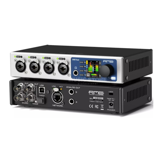
RME AVB Tool User’s Guide 3. Hardware Analog Input Connectors Control Section Headphone Output Standby Switch USB 2.0 Type B Jack Security Lock Slot Word Clock MADI Coaxial and SFP Network Connection Analog Line Level Outputs Power supply 7 | 3. Hardware... -
Page 13: Hardware Specifications
3. If the device is in standby mode, hold the encoder for two seconds to boot the device. The AVB Tool features a dark mode which deactivates some or all lights of the front panel. ... - Page 14 RME AVB Tool User’s Guide Possible actions: • When the device is in standby mode, pushing the encoder for two seconds will boot the device. • When the device is powered on, push and hold the encoder for several seconds in order to power down the device.
-
Page 15: Standby Indicator
RME AVB Tool User’s Guide 3.5. Standby Indicator The following illumination patterns are possible: No illumination • There is no power at the DC input. • Dark mode has been activated. Permanent red illumination • The device is powered off but is receiving power at either one of the power inlets. -
Page 16: Analog Input Connectors
RME AVB Tool User’s Guide 3.6. Analog Input Connectors XLR/TRS combo jacks 1-4 On the front of the device, four combined XLR/TRS inputs labeled "1" to "4" can be used for microphone, line and instrument signals. Phantom power (48 V) for microphones can be activated on each XLR input, high impedance ("Hi-Z") can be activated when using unbalanced TS connectors. -
Page 17: Frequency And Impulse Response
• Switchable high impedance (unbalanced TS): 1 MOhm 3.7. Frequency and Impulse Response The A/D converters of the AVB Tool are optimized for extremely low latencies (Short Delay IIR filters). At single speed, the conversion prioritizes frequency response to ensure linear conversion across the entire frequency band. - Page 18 RME AVB Tool User’s Guide Color Color name dBFS Orange Red flashing fast 0 (at least three consecutive samples) Red flashing slow Input muted 13 | 3.9. Meter Backlight Color and Intensity Reference...
-
Page 19: Control Section
Standby Switch, Encoder The AVB Tool can be configured completely at the device. To do so, the a TFT display shows a menu. The adjacent encoder knob and buttons are used to navigate and change settings. In addition, each input channel has a dedicated button to access its controls. -
Page 20: Headphone Output
3.11. Headphone Output The AVB Tool features a stereo headphone output, 1/4" (6.3mm) TRS on the front panel. It can also function as a dual mono unbalanced output (13 dBu) and as a mono balanced line level output (19 dBu). -
Page 21: Power Supply
RME AVB Tool User’s Guide 3.12. Power supply The AVB Tool comes with an external 12 V 2.0 A power supply with a locking connector (5.5 mm positive polarity) and detachable power cord (C7). Insert the connector fully with the lock tabs facing sideways, then gently turn 30 degrees clockwise to secure the connector in place. -
Page 22: Network Connection
RME AVB Tool User’s Guide 3.14. Network Connection On the rear of the AVB Tool, a ruggetized RJ45 connector labeled NETWORK provides ethernet connectivity. The supported link speed is 1 Gb/s for AVB. A green LED (left, LINK) signals network traffic (blinking). A yellow LED (right, ACT) signals a successful link. -
Page 23: Usb 2.0 Type B Jack
3.16. USB 2.0 Type B Jack The USB jack at the rear of the AVB Tool provides an alternative connection method for web remote control when a network connection is not available. When connecting the AVB Tool with a standard ("printer") USB 2.0 cable to a current Microsoft Windows™... - Page 24 RME AVB Tool User’s Guide the URL http://172.20.0.1. The USB port cannot be used to stream audio signals. 19 | 3.16. USB 2.0 Type B Jack...
-
Page 25: Analog Line Level Outputs
RME AVB Tool User’s Guide 3.17. Analog Line Level Outputs Two 1/4" (6.3mm) TRS balanced line level outputs (labelled 3 and 4) are located on the rear panel. They support +4 dBu and +19 dBu line level. Any digital or analog input signal can be sent to these outputs. The outputs are servo balanced, therefore unbalanced cables with TS plugs can be used and deliver the same output level as balanced connections. -
Page 26: Accessories
RME AVB Tool User’s Guide 4. Accessories RME offers optional accessories for the AVB Tool: Part Number Description SFP Modules MADI-SFP-MM MADI optical multi-mode module, 2 km, LC MADI-SFP-SM MADI optical single-mode module, 20 km, LC 21 | 4. Accessories... -
Page 27: Avb Connectivity
RME AVB Tool User’s Guide 5. AVB Connectivity Network Control The AVB Tool is an AVB endpoint device that can be configured with the IEEE Standard for Device Discovery, Connection Management, and Control Protocol for IEEE 1722™ Based Devices, in short: AVDECC. -
Page 28: Changing The Device Name
RME AVB Tool User’s Guide 1. Open the AVB Tool web remote in a browser (see Finding the Device on a Network]) 2. Press the identify icon. The front panel level meters of the controlled device will show an animation. -
Page 29: Adjusting The Network Latency
The AVB Tool offers a freely adjustable presentation time offset for each output stream. In AVB networks, the latency is always specified by the talker and guaranteed by the ... -
Page 30: Quick Start (Madi)
RME AVB Tool User’s Guide 6. Quick Start (MADI) Follow this procedure to send microphone input signals to the digital outputs. 1. Load Preset 1 from the STATE>Preset tab. If 2. In the CLOCK section, choose a sample rate Preset 1 has been modified, load the Factory... -
Page 31: Warranty And Support
The distributor does not accept claims for damages of any kind, especially consequential damage. Liability is limited to the value of the AVB Tool. The general terms of business drawn up by the distributor apply at all times. -
Page 32: Support Contacts
RME AVB Tool User’s Guide 7.3. Support Contacts Additionally, the following global service centers can provide support assistance: Europe Audio AG, Germany support@rme-audio.de Synthax U.K. info@synthax.co.uk Asia/Australia RME Trading Ltd., Hong Kong support@rme-trading.hk Americas Synthax Inc., U.S.A. tech.support@synthax.com Global support@rme-audio.de... -
Page 33: State Section
• Remote control Quick Start Preset Pressing and holding the first (top) button next to the display while powering on the AVB Tool (and until the channel LEDs start flashing) activates the Quick Start Preset. Loading this preset does not affect any internally saved presets until it is saved. -
Page 34: Saving Presets
3. Push Save to save the preset. 8.1.2. Loading Presets Up to 15 custom presets can be loaded from the internal storage of the AVB Tool. Loading a preset cannot be undone. Ensure that any important configuration has been ... -
Page 35: Loading Factory Default Settings
STATE section. 8.2. Device Lock The AVB Tool can be secured against both accidental and intentional changes to its configuration. Locking the device, with or without code, protects against changes on the device itself. When locked, the display shows a lock symbol. -
Page 36: Unlocking The Device
4. (optional) Move the encoder onto the lock code (if any), and push the encoder to delete it. 8.3. Front Panel Illumination The AVB Tool front panel illumination reveals the current device state at a glance. It combines: • full color LEDs at each input •... -
Page 37: Dark Mode
RME AVB Tool User’s Guide 8.3.1. Dark Mode Each of the three front panel illumination sections can be switched off if they are not required. To turn off illumination on the device: 1. Open the visual feedback tab in the STATE section. -
Page 38: Persistent Clipping Notifications And Peak Hold
RME AVB Tool User’s Guide To change the metering mode on the device: 1. Open the visual feedback tab in the STATE section. 2. Open "Global Meters" using the corresponding button. 3. Press the first button to toggle between Peak and RMS metering. -
Page 39: Metering Of Digital Signals
RME AVB Tool User’s Guide To switch over notifications on or off: 1. Open the visual feedback tab in the STATE section 2. Change Peak Hold to either: ◦ 5s to notify for five seconds ◦ On to notify until manually reset ◦... -
Page 40: Remote Control Overview
3. Turn the encoder knob to step through the input and output signals. 8.4. Remote Control Overview The AVB Tool can be remote controlled. Remote control is activated by default and is not affected by preset changes or device lock. - Page 41 2. Ensure that the HTTP Remote setting is switched to When the device is connected with a USB 2.0 cable to a Apple macOS™ or Microsoft Windows™ computer, a network device is automatically installed in the background that assigns the AVB Tool the following IP address: http://172.20.0.1...
-
Page 42: Web Remote
RME AVB Tool User’s Guide 8.4.2. Web Remote An integrated web server provides an easy-to-use remote control interface for the AVB Tool. It requires a network connection from a desktop or tablet computer with a current browser version. Due to the amount of features, the web remote manual has been separated from this ... -
Page 43: Json(Osc) Remote Control
Control protocol. Detailed background information on the underlying technology can be found on the Sennheiser® website. The AVB Tool can be remote controlled with HTTP POST requests. Each request carries a data payload that contains a JSON object modeled after the open sound control (OSC) protocol. - Page 44 RME AVB Tool User’s Guide Request: curl --header "Content-Type: application/json" --request POST --data '{"osc":{"schema":null}}' avb-tool.local/api/v2/self Response: "osc": { "schema": { "osc": { "version": null, "schema": [] "device": { "entity_id": null, "entity_model_id": null, ...
-
Page 45: Json(Osc) Implementation Chart
RME AVB Tool User’s Guide Executing this command delivers the expected result: {"device":{"vendor_name":"RME Audio"}} The entire web remote application is based on this protocol. It is therefore possible to read the data payloads sent to the device when interacting with the web remote by using the "Network"-tab of the developer tools inside the browser. -
Page 46: Device Information
RME AVB Tool User’s Guide 8.5. Device Information The information tab is located in the STATE section. It shows the current device name, firmware version and gPTP Grandmaster ID. 41 | 8.5. Device Information... -
Page 47: Input Section
9.1. Analog Inputs The analog inputs of the AVB Tool can be configured at the device or remotely. Gain, phase, phantom power (48V) and TRS can be set on all inputs. While switched to TRS, the impedance can be set to High-Z for instrument signals. -
Page 48: Analog Input User Interfaces
RME AVB Tool User’s Guide 9.1.1. Analog Input User Interfaces Each analog input channel at the device has its own button. The button activates a settings dialog on the screen. Activate channel controls Monitor to phones Gain Groups and Phase... -
Page 49: Enabling Phantom Power (P48)
RME AVB Tool User’s Guide 9.1.3. Enabling Phantom Power (P48) Channels with active phantom power are shown on the standby-screen with a yellow square indicator. To activate phantom power on several channels: 1. While the standby screen shows the input level meters, press and hold the first button next to the yellow indicator. -
Page 50: Switching Between Xlr And Trs Inputs
RME AVB Tool User’s Guide 9.1.4. Switching Between XLR and TRS Inputs The input channels 1-4 have "combo-jacks" that support both XLR and TRS connectors. When a plug is inserted, the corresponding input must be selected in the input settings. XLR is the default choice in the factory preset. -
Page 51: Activating High Impedance (Hi-Z) On Trs Inputs
RME AVB Tool User’s Guide To toggle between XLR and TRS inputs on several channels: 1. While the standby screen shows the input level meters, press and hold the second button next to the X|T indicator. An instruction is shown on the display and the LEDs next to the input channels change to off (XLR) or white (TRS). -
Page 52: Inverting The Phase Of An Analog Input Signal
RME AVB Tool User’s Guide To activate high impedance on several channels: 1. While the standby screen shows the input level meters, press then hold down the first button. An instruction is shown on the display and the LEDs next to the TRS input channels change to white (low impedance) or blue (high impedance). -
Page 53: Gain Groups
RME AVB Tool User’s Guide To toggle the phase of an input signal 1. Use the button next to the corresponding input to access its settings. 2. On a combined XLR/TRS input, press the third button twice in quick succession (double press). The phase button Ø... -
Page 54: Creation And Use Of A Gain Group
RME AVB Tool User’s Guide It is possible to adjust the gain of individual channels even when they are part of a gain group. 9.1.8. Creation and Use of a Gain Group To create a group that controls the gain of two or more channels at once, proceed with the following steps: the group can include TRS inputs that have a different gain range. -
Page 55: Saving, Using And Deleting Gain Groups
9.1.10. Monitor Analog Inputs at Phones Output The phones output at the front of the AVB Tool can receive any input signal. Permanent routings are configured in the Phones Output settings (see Routing Signals to the Outputs and Phones Output). -
Page 56: Madi Input
• by opening the phones output and deactivating the mode there. If there was a previous routing, it will be re-established immediately. 9.2. MADI Input The AVB Tool accepts up to two MADI signals, one electrical (BNC input) and one optical via SFP option (LC input). To connect a MADI signal: 1. -
Page 57: Connecting Two Identical Madi Signals For Redundancy
For a seamless failover, the two MADI signals must be identical. However, only the SYNC and LOCK states are evaluated to confirm the current input state. It is therefore possible to send two different signals to the AVB Tool as long as they are in sync. 9.2. MADI Input | 52... -
Page 58: Avb Input Streams
4. Connect both MADI signals with identical audio. 9.3. AVB Input Streams The AVB streams received by the AVB Tool are referred to as "input streams". For these streams, the device acts as an AVB Listener. To establish a connection between a talker and a listener, an AVDECC Controller is required. The AVB Tool does not include an AVDECC Controller. - Page 59 RME AVB Tool User’s Guide To change the amount of channels and format of incoming AVB streams: 1. Open the AVB tab in the INPUT section. 2. Use the first button and encoder to select an incoming stream. 3. Use the second button and encoder to change the stream size and format.
-
Page 60: Output Section
Example: In the OUTPUT section, MADI Optical 1-12 is chosen as source for AVB Stream 2. The AVB Tool is clock master, but the incoming MADI signal is not correctly synchronized. This causes a warning in the INPUT section. -
Page 61: Analog Outputs
RME AVB Tool User’s Guide To create a routing to a MADI Coaxial output: 1. Open the routing tab of the MADI Coaxial output in the OUTPUT section (see Use of the Display and Encoder). 2. Activate the routing destination and choose an output channel with the encoder (steps 1 and 2). -
Page 62: Muting The Phones Output
RME AVB Tool User’s Guide To adjust the headphone volume on the device: 1. While on the main screen, rotate the encoder. The current volume will be shown below the encoder on the screen. To separate the left and right headphone channels: 1. -
Page 63: Using Phones Out As A Balanced Line Output
RME AVB Tool User’s Guide 10.2.4. Using Phones Out as a Balanced Line Output The headphone output can operate as a mono balanced line level output. This may for example be useful when an active talkback speaker with symmetrical input is connected to the 12Mic. -
Page 64: Madi Outputs
10.3. MADI Outputs The MADI outputs of the AVB Tool are always active. If no routing is configured, an empty stream is sent that can be used for clocking. The state without routing is represented with a light-green Status Indicator. -
Page 65: Madi Daisy Chains
10.4. AVB Output Streams The AVB streams leaving the AVB Tool are described as "output streams". In this case, the device acts as a talker. The talker defines the presentation time and therefore the latency across the network. This is set per default to 2 ms. -
Page 66: Change Avb Output Stream Size And Format
RME AVB Tool User’s Guide Description Indicator Possible solution Disabled grey Create routing Disabled orange Create connection with AVDECC controller Streaming/Transmitting green SR mismatch Verify that the sample rates of talker and listener are identical Waiting yellow … Wait for listener to be ready... - Page 67 RME AVB Tool User’s Guide Changing stream sizes is not possible when streams are connected. 10.4. AVB Output Streams | 62...
-
Page 68: Clock Section
RME AVB Tool User’s Guide 11. CLOCK Section The CLOCK section is used to inspect and configure the clock source and sample rate of the AVB Tool. 11.1. Clock status The clock of all digital inputs is continuously monitored with SyncCheck™ and shown in the CLOCK section. -
Page 69: Selecting A Master Clock
3. Rotate the encoder until the preferred clock source is shown. 4. Push the encoder again to activate the setting. 11.3. Sample Rates Overview The AVB Tool supports the following sample rates: Supported sample rates Single speed 44.1 kHz, 48 kHz Double speed 88.2 kHz, 96 kHz... -
Page 70: Number Of Channels
RME AVB Tool User’s Guide MADI 88.2 96 with warning MADI MADI 176.4 192 with warning MADI MADI 96k 88.2 44.1 warning (no sync) MADI 96k 88.2 warning (no sync) MADI 96k 88.2 88.2 88.2 MADI 96k 88.2 88.2 with warning MADI 96k 88.2... -
Page 71: Selecting A Sample Rate
11.3.4. Effects of Sample Rate Changes on Existing Routing The AVB Tool saves one routing table per preset, regardless of sample rate. A change of sample rate or MADI frame mode can reduce the number of input and output channels available for routing. This does not alter the routing table. - Page 72 RME AVB Tool User’s Guide first 14 channels of MADI coaxial input are routed to the optical output. Switching the sample rate to 44.1 or 48 kHz will reveal the previous routing for 32 channels. 67 | 11.3. Sample Rates Overview...
-
Page 73: Set Word Clock Output To Single Speed
RME AVB Tool User’s Guide 11.4. Set Word Clock Output to Single Speed At sample rates > 48 kHz, it may be necessary to synchronize two devices with a fraction of the actual sample rate: Sample Rate Word Clock Full Speed (default) Word Clock Single Speed (option) 88.2 kHz... -
Page 74: Annex
RME AVB Tool User’s Guide 12. Annex Trademarks and Copyright All trademarks, registered or otherwise, are the property of their respective owners. RME is a registered trademark of RME Intelligent Audio Solutions. SyncCheck, SteadyClock, ICC, Intelligent Clock Control and Digiface are trademarks of RME Intelligent Audio Solutions. -
Page 75: Glossary
RME AVB Tool User’s Guide Glossary 96k frame MADI sources with a sample rate of 88.2kHz or 96kHz can be configured to use the so-called 96k frame. If this frame is used, a sample rate of 88.2 or 96 kHz can be detected on the receiver side automatically. -
Page 76: Ce Compliance
Responsible Party in USA: Synthax United States, 6600 NW 16th Street, Suite 10, Ft Lauderdale, FL 33313 T.:754.206.4220 Trade Name: RME, Model Number: AVB Tool Note on Disposal According to the guide line RL2002/96/EG (WEEE – Directive on Waste Electrical and Electronic Equipment), valid for all european countries, this product has to be recycled at the end of its lifetime. - Page 77 RME AVB Tool User’s Guide Scheck Audio GmbH, 3. Industriestr. 5, 68804 Altlussheim, Germany. Shipments not prepaid will be rejected and returned on the original sender’s costs. Glossary | 72...
Need help?
Do you have a question about the AVB Tool and is the answer not in the manual?
Questions and answers